Isuzu KB P190. Manual — part 593
6E–202
ENGINE DRIVEABILITY AND EMISSIONS
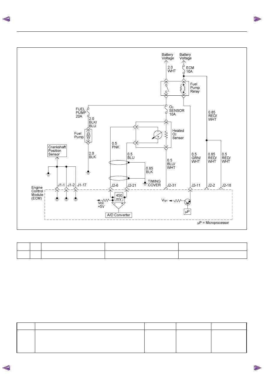
DIAGNOSTIC TROUBLE CODE (DTC) P0562 SYSTEM VOLTAGE LOW
Condition for setting the DTC and action taken when the DTC sets
Circuit Description
The engine control module (ECM) monitors the system
voltage on the ignition feed terminal to the ECM. A
system voltage Diagnostic Trouble Code will set
whenever the voltage is below a calibrated value.
Diagnostic Aids
• If the Diagnostic Trouble Code sets when an
accessory is operated, check for a poor connection or
excessive current draw.
• Check for open circuits or shorts to ground on the
ECM’s battery or ignition inputs.
Diagnostic Trouble Code (DTC) P0562 System Voltage Low
Code
Type
DTC Name
DTC Setting Condition
Fail-Safe (Back Up)
P0562
D
System Voltage Low
Battery voltage is below 11V.
No fail-safe function.
Step
Action
Value(s)
Yes
No
1
Was the “On-Board Diagnostic (OBD) System Check”
performed?
—
Go to Step 2
Go to On Board
Diagnostic
(OBD) System
Check
ENGINE DRIVEABILITY AND EMISSIONS
6E–203
2
1. Connect the Tech 2.
2. Review and record the failure information.
3. Select “F0: Read DTC Infor By Priority” in “F0:
Diagnostic Trouble Code”.
Is the DTC P0562 stored as “Present Failure”?
—
Go to Step 3
Refer to
Diagnostic Aids
and Go to Step
3
3
1. Using the Tech2, ignition “On” and engine “Off”.
2. Select “Clear DTC Information” with the Tech2 and
clear the DTC information.
3. Operate the vehicle and monitor the “F5: Failed
This Ignition” in “F2: DTC Information”.
Was the DTC P0562 stored in this ignition cycle?
—
Go to Step 4
Refer to
Diagnostic Aids
and Go to Step
4
4
1. Using the Tech 2, ignition “On” and engine “On”.
2. Monitor the “Ignition Voltage” in the data display.
3. Load the electrical system by turning on the
headlights, etc..
Does the Tech 2 indicate enough ignition voltage?
10 - 14.5V
Go to Step 6
Go to Step 5
5
Using the DVM and check the battery voltage at the
battery terminal.
Does the tester indicate enough battery voltage?
10 - 14.5V
Go to Step 6
Check the
charging
system, charge
or replace the
battery
6
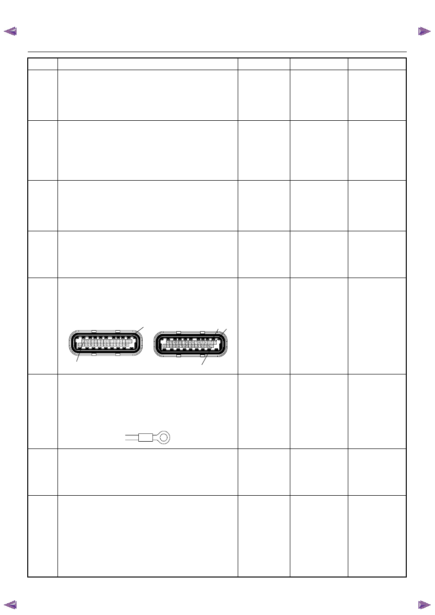
Check for poor/faulty connection at the ECM
connector. If a poor/faulty connection is found, repair
as necessary.
Was the problem found?
—
Verify repair
Go to Step 7
7
Check for poor/faulty connection of the ECM ground
at the inlet manifold. If a poor/faulty connection is
found, repair as necessary.
Was the problem found?
—
Verify repair
Go to Step 8
8
Is the ECM programmed with the latest software
release?
If not, download the latest software to the ECM using
the “SPS (Service Programming System)”.
Was the problem solved?
—
Verify repair
Go to Step 9
9
Replace the ECM.
Is the action complete?
IMPORTANT: The replacement ECM must be
programmed. Refer to section of the Service
Programming System (SPS) in this manual.
Following ECM programming, the immobilizer system
(if equipped) must be linked to the ECM. Refer to
section 11 “Immobilizer System-ECM replacement” for
the ECM/Immobilizer linking procedure.
—
Verify repair
—
Step
Action
Value(s)
Yes
No
16
2
17
1
2
C-56(J2)
E-60(J1)
E-72
6E–204
ENGINE DRIVEABILITY AND EMISSIONS
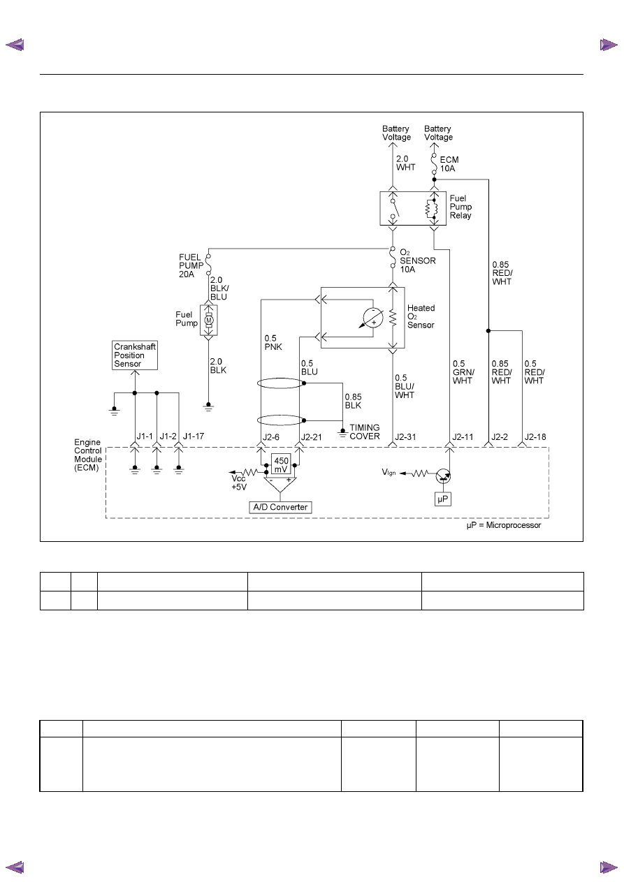
DIAGNOSTIC TROUBLE CODE (DTC) P0563 SYSTEM VOLTAGE HIGH
Condition for setting the DTC and action taken when the DTC sets
Circuit Description
The engine control module (ECM) monitors the system
voltage on the ignition feed terminals to the ECM. A
system voltage Diagnostic Trouble Code will set
whenever the voltage is above a calibrated value.
Diagnostic Aids
Check for a faulty charging system components.
Diagnostic Trouble Code (DTC) P0563 System Voltage High
Code
Type
DTC Name
DTC Setting Condition
Fail-Safe (Back Up)
P0563
A
System Voltage High
Battery voltage is above 16V.
No fail-safe function.
Step
Action
Value(s)
Yes
No
1
Was the “On-Board Diagnostic (OBD) System Check”
performed?
—
Go to Step 2
Go to On Board
Diagnostic
(OBD) System
Check

ENGINE DRIVEABILITY AND EMISSIONS
6E–205
2
1. Connect the Tech 2.
2. Review and record the failure information.
3. Select “F0: Read DTC Infor By Priority” in “F0:
Diagnostic Trouble Code”.
Is the DTC P0563 stored as “Present Failure”?
—
Go to Step 3
Refer to
Diagnostic Aids
and Go to Step
3
3
1. Using the Tech2, ignition “On” and engine “Off”.
2. Select “Clear DTC Information” with the Tech2 and
clear the DTC information.
3. Operate the vehicle and monitor the “F5: Failed
This Ignition” in “F2: DTC Information”.
Was the DTC P0563 stored in this ignition cycle?
—
Go to Step 4
Refer to
Diagnostic Aids
and Go to Step
4
4
1. Using the Tech 2, ignition “On” and engine “On”.
2. Monitor the “Ignition Voltage” in the data display.
3. Load the electrical system by turning on the
headlights, etc..
Does the Tech 2 indicate correct ignition voltage?
Less than 16V
Go to Step 5
Check the
charging
system and Go
to Step 5
5
Is the battery jamp start cable incorrectly connecting?
—
Verify
procedure
Go to Step 6
6
Is the ECM programmed with the latest software
release?
If not, download the latest software to the ECM using
the “SPS (Service Programming System)”.
Was the problem solved?
—
Verify repair
Go to Step 7
7
Replace the ECM.
Is the action complete?
IMPORTANT: The replacement ECM must be
programmed. Refer to section of the Service
Programming System (SPS) in this manual.
Following ECM programming, the immobilizer system
(if equipped) must be linked to the ECM. Refer to
section 11 “Immobilizer System-ECM replacement” for
the ECM/Immobilizer linking procedure.
—
Verify repair
—
Step
Action
Value(s)
Yes
No
Нет комментариевНе стесняйтесь поделиться с нами вашим ценным мнением.
Текст