Isuzu KB P190. Manual — part 591

6E–194
ENGINE DRIVEABILITY AND EMISSIONS
9
Using the DVM and check the purge solenoid valve
signal circuit.
1. Ignition “On”, engine “Off”.
2. Disconnect the purge solenoid valve connector.
3. Check the circuit for short to voltage circuit.
Was the DVM indicated voltage?
—
Repair faulty
harness and
verify repair
Go to Step 10
10
Substitute a known good purge solenoid valve and
recheck.
Was the problem solved?
—
Go to Step 11
Go to Step 12
11
Replace the purge solenoid valve.
Was the problem solved?
—
Verify repair
Go to Step 12
12
Is the ECM programmed with the latest software
release?
If not, download the latest software to the ECM using
the “SPS (Service Programming System)”.
Was the problem solved?
—
Verify repair
Go to Step 13
13
Replace the ECM.
Is the action complete?
IMPORTANT: The replacement ECM must be
programmed. Refer to section of the Service
Programming System (SPS) in this manual.
Following ECM programming, the immobilizer system
(if equipped) must be linked to the ECM. Refer to
section 11 “Immobilizer System-ECM replacement” for
the ECM/Immobilizer linking procedure.
—
Verify repair
—
Step
Action
Value(s)
Yes
No
V
E-66
1
ENGINE DRIVEABILITY AND EMISSIONS
6E–195
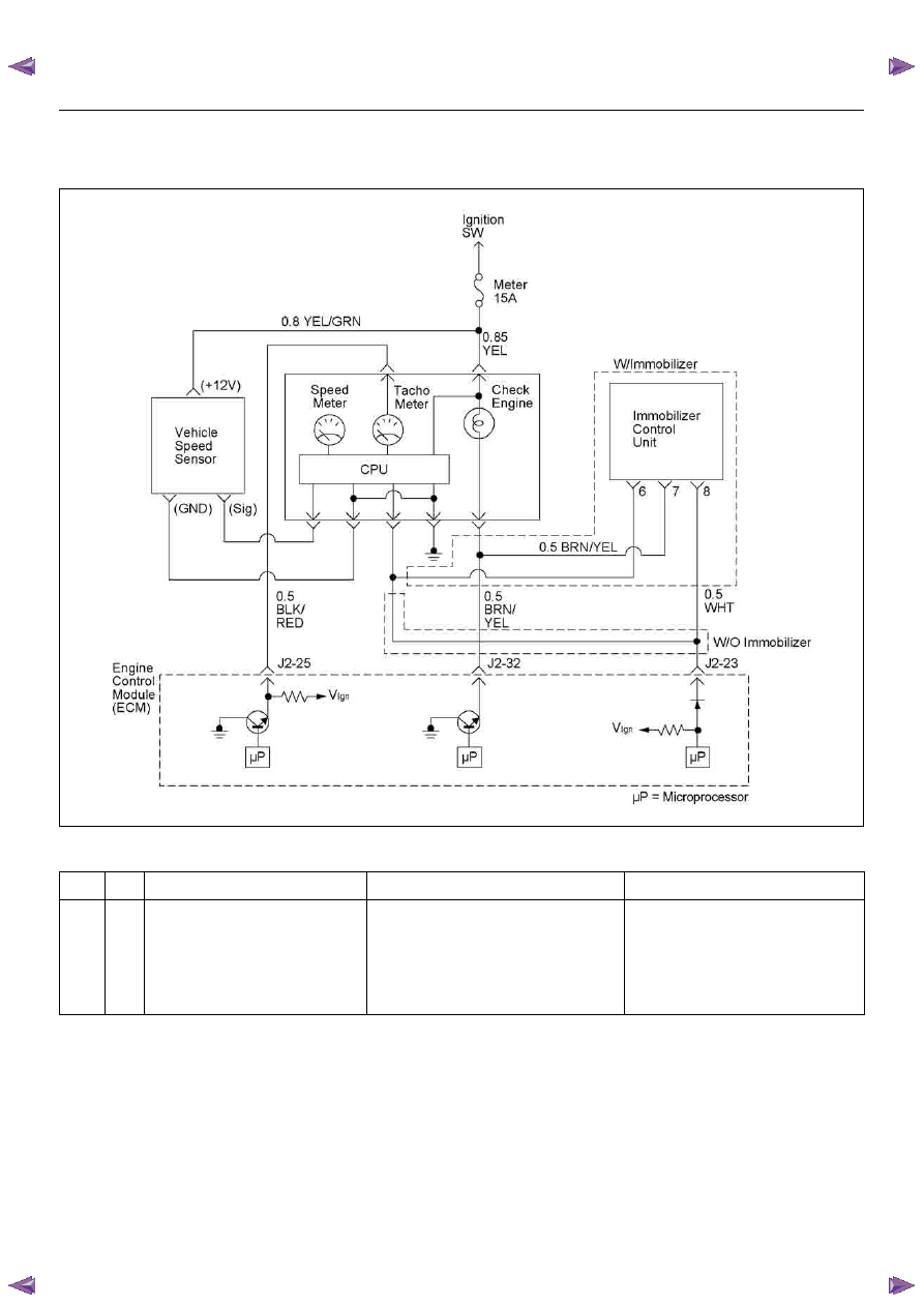
DIAGNOSTIC TROUBLE CODE (DTC) P0502 VEHICLE SPEED SENSOR (VSS)
CIRCUIT LOW INPUT
Condition for setting the DTC and action taken when the DTC sets
Circuit Description
The vehicle speed sensor has a magnet rotated by the
transmission output shaft. Attached to the sensor is a
hall effect circuit that interacts with the magnetic field
created by the rotating magnet. A 12-volt operating
supply for the speed sensor hall circuit is supplied from
the meter fuse.
Diagnostic Aids
• Poor connection at ECM: Inspect harness connectors
for backed out terminals, improper mating, broken
locks, improperly formed or damaged terminals, and
poor terminal to wire connection.
Code
Type
DTC Name
DTC Setting Condition
Fail-Safe (Back Up)
P0502
B
Vehicle Speed Sensor Circuit Low
Input
1. No DTC relating to MAP sensor, TPS, ECT
sensor, injector control circuit and ignition
control circuit.
2. Engine is running.
3. Vehicle speed is below 3km/h in power
condition or 2km/h in deceleration condi-
tion.
ECM uses 0km/h condition as substitute.
6E–196
ENGINE DRIVEABILITY AND EMISSIONS
Diagnostic Trouble Code (DTC) P0502 Vehicle Speed Sensor Circuit Low Input
Step
Action
Value(s)
Yes
No
1
Was the “On-Board Diagnostic (OBD) System Check”
performed?
—
Go to Step 2
Go to On Board
Diagnostic
(OBD) System
Check
2
1. Connect the Tech 2.
2. Review and record the failure information.
3. Select “F0: Read DTC Infor By Priority” in “F0:
Diagnostic Trouble Code”.
Is the DTC P0502 stored as “Present Failure”?
—
Go to Step 3
Refer to
Diagnostic Aids
and Go to Step
3
3
1. Using the Tech2, ignition “On” and engine “Off”.
2. Select “Clear DTC Information” with the Tech2 and
clear the DTC information.
3. Operate the vehicle and monitor the “F5: Failed
This Ignition” in “F2: DTC Information”.
Was the DTC P0502 stored in this ignition cycle?
—
Go to Step 4
Refer to
Diagnostic Aids
and Go to Step
4
4
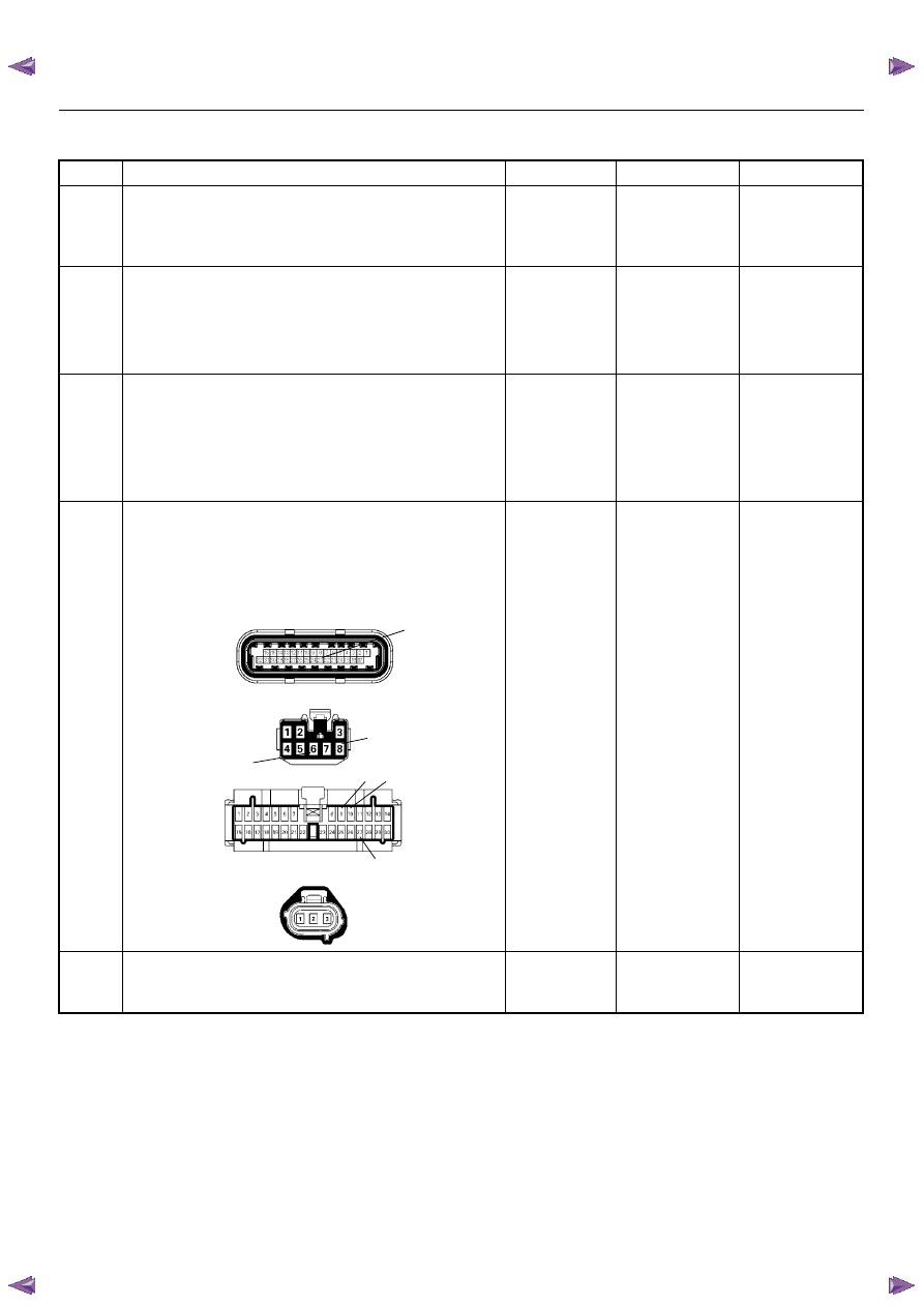
Check for poor/faulty connection at the VSS, meter,
immobilizer control unit (if equipped), ECM and other
connectors. If a poor/faulty connection is found, repair
the faulty terminal.
Was the problem found?
—
Verify repair
Go to Step 5
5
Remove the VSS from the housing case and visually
check.
Was the problem found?
—
Go to Step 19
Go to Step 6
6
8
23
27
9 10
C-56(J2)
B-68
B-24
E-44
ENGINE DRIVEABILITY AND EMISSIONS
6E–197
6
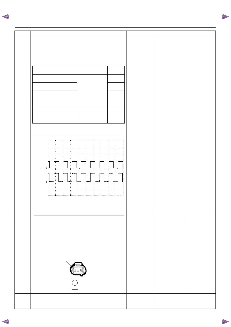
Using the DVM and check the VSS signal.
1. Ignition “On”, vehicle “Run (lift up)”.
2. Measure the VSS output voltage at sensor, meter,
immobilizer control unit (if equipped) and ECM.
Does the tester indicate specified value?
If a oscilloscope is available, monitor the VSS signal.
Does the oscilloscope indicate correct wave form?
Refer to
Diagnostic Aids
and Go to Step
21
Refer the table
7
Using the DVM and check the VSS power supply
circuit.
1. Ignition “On”, engine “Off”.
2. Disconnect the VSS connector.
3. Check the circuit for open or short to ground
circuit.
Was the DVM indicated specified value?
10 - 14.5V
Go to Step 9
Go to Step 8
8
Repair the open circuit between the VSS and meter
fuse.
Is the action complete?
—
Verify repair
—
Step
Action
Value(s)
Yes
No
Measurement Position
Voltage (V)
(AC Range)
If No
Good
VSS terminal 3 & GND
Approximately
7.0 V at 20km/h
Go to
Step 7
Meter B24 connector 9 &
GND
Go to
Step 11
Meter B24 connector 10 &
GND
Go to
Step 13
Immobilizer control unit B68
connector 6 & GND
Go to
Step 14
Immobilizer control unit B68
connector 8 & GND
Approximately
6.5V at 20km/h
Go to
Step 16
ECM C56 (J2) connector 23 &
GND
Go to
Step 17
Vehicle Speed Sensor (VSS) Reference W ave Form
CH1
0V
CH2
0V
Measurement Terminal: CH1: ECM J2-23(+) / CH2: VSS 3(+)
GND(-)
Measurement Scale: CH1: 10V/div / CH2: 10V/div 50ms/div
Measurement Condition: Approximately 20km/h
Note: The vehicle is without immobilizer system,
CH1 signal is same as CH2.
V
E-44
1
Нет комментариевНе стесняйтесь поделиться с нами вашим ценным мнением.
Текст