Isuzu KB P190. Manual — part 1202
7C-30 CLUTCH
RTW57CSH000201
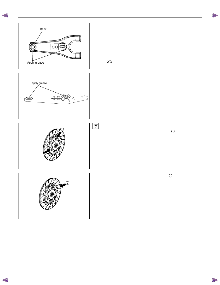
Shift Fork
1. Visually inspect the surfaces of the shift fork making contact
with the release bearing for excessive wear and damage.
2. Remove any minor stepping or abrasion from the release
bearing with an oil stone.
Replace any exhibiting excessive wear or damage.
3. Apply multi-purpose type grease (NLGI No.2 or No.3) to
area.
RTW57CSH000501
DRIVEN PLATE ASSEMBLY
1. Visually inspect the torsion spring
1
for looseness,
breakage, and weakening.
If any of these conditions are discovered, the driven plate
assembly must be replaced.
2. Visually inspect the facing surfaces
2
for cracking and
excessive scorching.
Visually inspect the facing surfaces for the presence of oil
or grease.
If any of these conditions are discovered, the facing must
be cleaned or replaced.
3. Check that the driven plate moves smoothly on the
transmission top gear shaft spline.
Minor ridges on the top gear shaft spline may be removed
with an oil stone.

CLUTCH 7C-31
Driven Plate Warpage
1. Insert the clutch pilot aligner into the driven plate splined
hub.
The clutch pilot aligner must be held perfectly horizontal.
Clutch Pilot Aligner : 5-8525-3001-0
2.
Set a dial indicator to the driven plate outside
circumference.
3. Slowly turn the driven plate.
Read the dial indicator as you turn the driven plate.
If the measured value exceeds the specified limit, the driven
plate assembly and/or the facing must be replaced.
Driven Plate Warpage
mm(in)
Standard
Limit
0.7 (0.028)
1.0 (0.039)
Driven Plate Splined Hub Spline Wear
1. Clean the driven plate splined hub.
2. Install the driven plate to the transmission top gear shaft
spline.
3. Set a surface gauge to the driven plate outside
circumference.
4. Slowly turn the driven plate counterclockwise.
Measure the spline rotation play as you turn the driven
plate.
If the measured value exceeds the specified limit, the driven
plate assembly must be replaced.
Driven Plate Splined Hub Spline Wear
mm(in)
Standard
Limit
0.5 (0.020)
1.0 (0.039)
Rivet Head Depression
Use a depth gauge or a straight edge with steel rule to
measure the rivet head depression
1
from the facing surface
2
.
Be sure to measure the rivet head depression on both sides of
the driven plate.
If the measured value is less than the specified limit, the facing
must be replaced.
Rivet Head Depression
mm(in)
Standard
Fly wheel side
P/Plate side
Limit
4J
series
1.35-1.95
(0.053-0.077)
1.65-2.25
(0.065-0.089)
0.2
(0.008)
C24SE
1.65-2.25
(0.065-0.089)
1.65-2.25
(0.065-0.089)
0.2
(0.008)
4JJ1
(High Output)
1.40-2.00
(0.055-0.079)
1.70-2.30
(0.067-0.091)
0.2
(0.008)
7C-32 CLUTCH
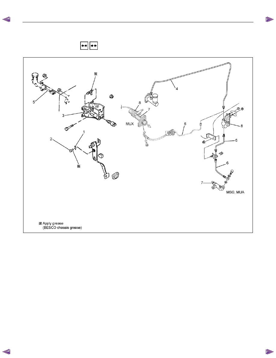
CLUTCH CONTROL
REMOVAL AND INSTALLATION
RTW77CLF000601
Removal Steps
1.
Pin
2. Jaw joint pin
3. Pedal assembly
4. Oil line
5. Master cylinder assembly
6. Oil line
7. Slave cylinder assembly
8. Damper cylinder assembly
Installation Steps
8. Damper cylinder assembly
7. Slave cylinder assembly
6. Oil line
5. Master cylinder assembly
4. Oil line
3. Pedal assembly
2. Jaw joint pin
1.
Pin
CLUTCH 7C-33
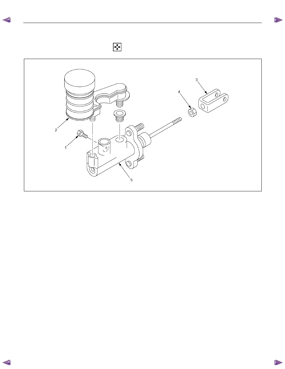
MASTER CYLINDER
DISASSEMBLY
Disassembly Steps
1. Bolt : reservoir tank
2. Reservoir tank
3.
Yoke
4. Lock nut
5. Body sub assembly
Нет комментариевНе стесняйтесь поделиться с нами вашим ценным мнением.
Текст