Isuzu KB P190. Manual — part 1201
7C-26 CLUTCH
INSPECTION AND REPAIR
Make the necessary adjustments, repairs, and part replacements if excessive wear or damage is discovered during
inspection.
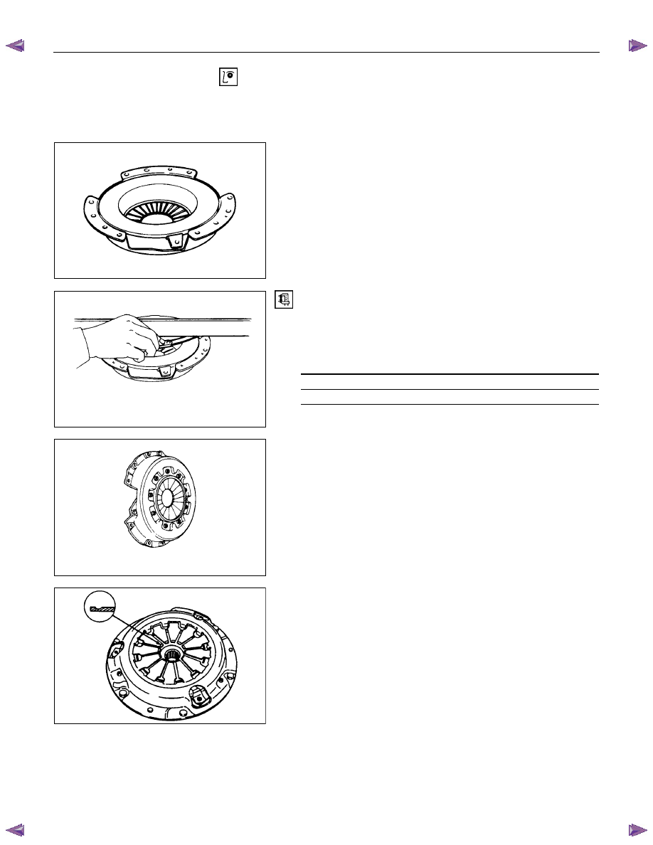
PRESSURE PLATE ASSEMBLY
Visually inspect the pressure plate friction surface for
excessive wear and heat cracks.
If excessive wear or deep heat cracks are present, the
pressure plate must be replaced.
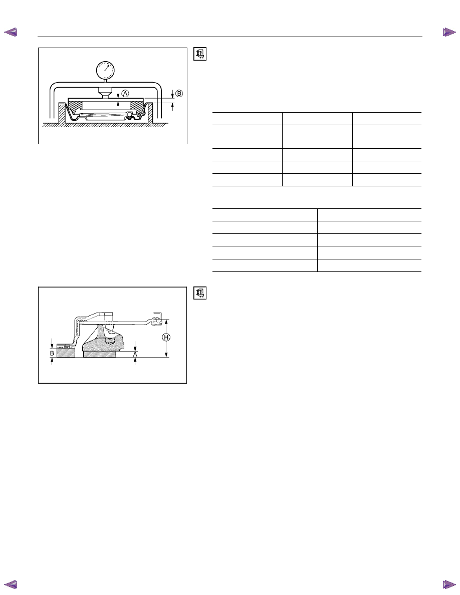
Pressure Plate Warpage
Use a straight edge and a feeler gauge to measure the
pressure plate friction surface flatness in four directions.
If any of the measured values exceed the specified limit, the
pressure plate must be replaced.
Pressure Plate Warpage
mm(in)
Limit
0.3 (0.012)
Clutch Cover
Visually inspect the entire clutch cover for excessive wear,
cracking , and other damage.
The clutch cover must be replaced if any of these conditions
are present.
1. Abrasion, scratches, cracks and deflection of friction face to
the disc, loose rivet and wear of ring
• Grind small scratches, or replace the assembly if extreme
scratches are found.
CLUTCH 7C-27
RTW67CSH000101
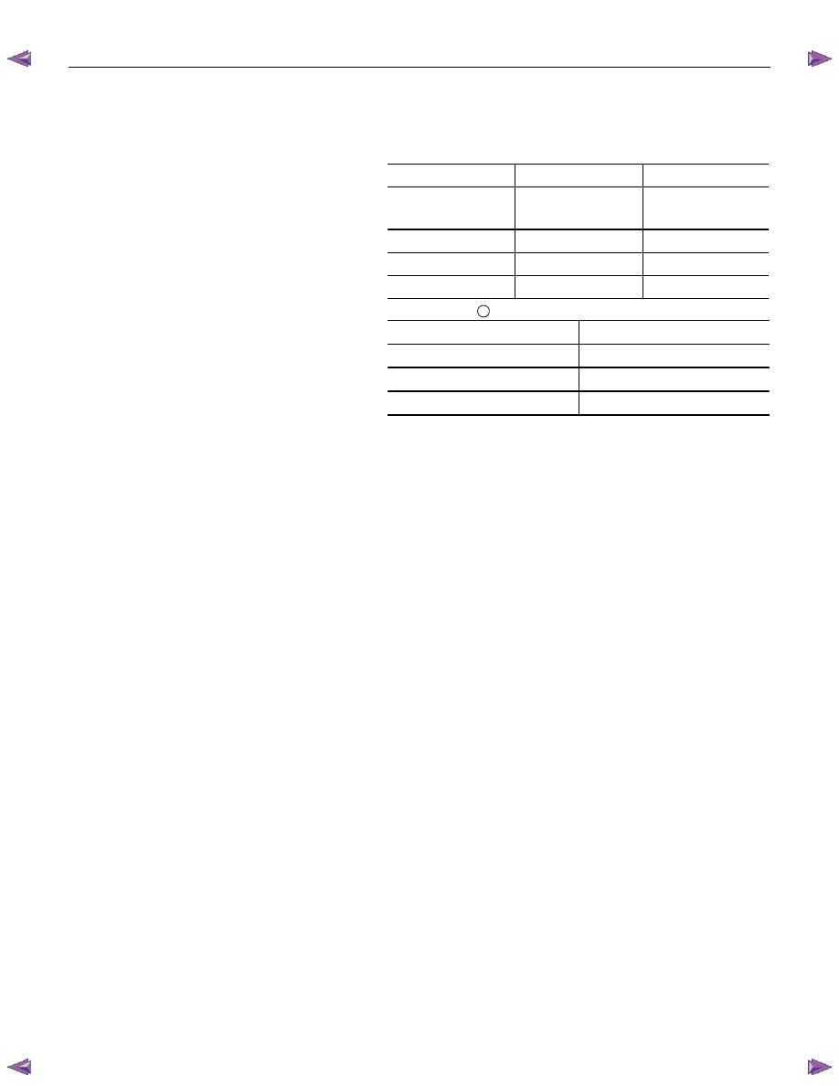
Clutch Set Force
1. Invert the pressure plate assembly.
2. Place a metal sheet “A” on the pressure plate.
3. Compress the pressure plate assembly until the distance
“B” becomes specified.
Thickness and Distance
mm(in)
A B
4JJ1 (High Output)
(MUX)
8.3 (0.327)
12 (0.472)
4JA1-T (MSG)
7.8 (0.307)
20 (0.787)
4J series (MUA)
7.8 (0.307)
18 (0.709)
C24SE (MUA)
8.0 (0.315)
7.9 (0.311)
4. Note the pressure plate gauge reading.
Driven Plate Clamping Load
N (kg/Ib)
Standard
4JJ1 (High Output) (MUX)
6860 (700/1544)
4JA1-T (MSG)
5070 (517/1140)
4J series (MUA)
6300 (642/1415)
C24SE (MUA)
5500 (561/1237)
RTW37CSH000101
Diaphragm Spring Finger Height
1. Place a new driven plate or the appropriate spacer beneath
the pressure plate.
2. Fully compress the pressure plate and diaphragm spring.
There are two ways to do this.
• Use a bench press to press down on the assembly from the
top.
• Tighten the fixing bolts.
NOTE: Preload on diaphragm spring finger must be 49 - 98 N
(11 - 22 lb) in direction of release, when clutch cover assembly
is bolted to the flywheel.
7C-28 CLUTCH
3. Measure the spring height from base to spring tip "H". If the
measured value exceeds the specified limit, the pressure
plate assembly must be replaced.
Spacer Thickness
mm(in)
A B
4JJ1 (High Output)
(MUX)
8.3 (0.327)
12 (0.472)
4JA1-T (MSG)
7.8 (0.307)
20 (0.787)
4J series (MUA)
7.8 (0.307)
18 (0.709)
C24SE (MUA)
8.0 (0.315)
7.9 (0.311)
Finger Height:
H
4JJ1 (High Output) (MUX)
49.9-51.9 (1.96-2.04)
4JA1-T (MSG)
31-33 (1.22-1.30)
4J series (MUA)
39-41 (1.54-1.61)
C24SE (MUA)
39-41 (1.54-1.61)
CLUTCH 7C-29
RTW77CSH000301
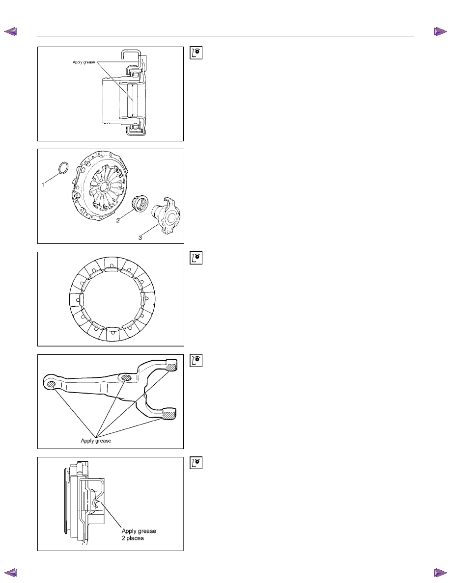
Release Bearing (MUX)
1. Visually check the release bearing for excessive play, noise
and breakage.
2. If any of these conditions are discovered, the release
bearing must be replaced.
3. Apply molybdenum disulfide grease to the areas shown in
illustration.
201RW010-X
4. When replacing the release bearing (3), replace both the
wedge collar (2) and wire ring (1) at the same time.
201RS013
Wedge Collar
1. Visually check the surfaces of the wedge collar making
contact with the release bearing for excessive wear and
damage.
2. Replace any exhibiting excessive wear or damage.
RTW77CSH000701
Shift Fork
1. Visually check the surfaces of the shift fork making contact
with the release bearing for excessive wear and damage.
2. Remove any minor stepping or abrasion from shift fork with
an oil stone.
3. Replace any exhibiting excessive wear or damage.
4. Apply molybdenum disulfide grease to the pin hole inner
circumferences and thrust surfaces.
RTW57CSH000401
Release Bearing (MSG, MUA)
1. Visually inspect the surfaces of the release bearing making
contact with the shift fork for excessive wear and damage.
Replace any exhibiting excessive wear or damage.
2. Apply multi-purpose type grease (NLGI No.2 or No.3) to
contact surface between the release bearing and the shift
fork. (Do not apply grease to the sleeve inner face.)
Нет комментариевНе стесняйтесь поделиться с нами вашим ценным мнением.
Текст