Isuzu KB P190. Manual — part 1030
ON-VEHICLE SERVICE (AW30–40LE) 7A3-35
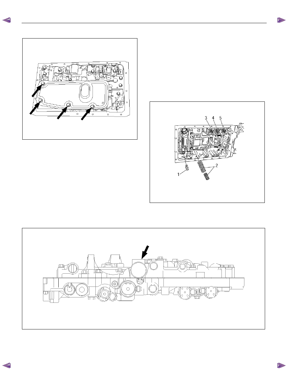
2. Remove the oil strainer assembly.
244RY00003
3. Disconnect the solenoid wiring connectors from the
solenoids.
4. Remove the twenty bolts from the valve body.
5. Remove the valve body assembly and pressure
control solenoid.
• After removing valve body assembly from the
transmission case, loosen the solenoid clamp
bolt and remove the pressure control solenoid
from the upper valve body assembly.
Also disconnect the harness connector from the
pressure control solenoid.
NOTE:
• Two or more persons are required for removal and
installation of the valve body assembly and pressure
control solenoid.
• The
check valve assembly (1) and the C0
accumulator piston springs (2) will fall from the
transmission case during removal of valve body
assembly.
Protect these parts from damage. The B0 (3), C2 (4),
and B2 (5) accumulator piston and springs may also
fall free and must be protected.
244RY00018
244RY00006
7A3-36 ON-VEHICLE SERVICE (AW30–40LE)
Installation
To install, follow the removal steps in reverse order
noting the following point;
1. Reinstall the parts removed with the valve body
assembly to their assigned positions in the
transmission case (check valve assembly, C0
accumulator pistons, etc). Install the valve body
assembly to the transmission case.
Refer to REASSEMBLY OF MAJOR
COMPONENTS (2).
2. Solenoid clamp bolt
Torque : 7 N
⋅⋅⋅⋅m (0.7 kgf⋅⋅⋅⋅m/61 Ib⋅⋅⋅⋅in)
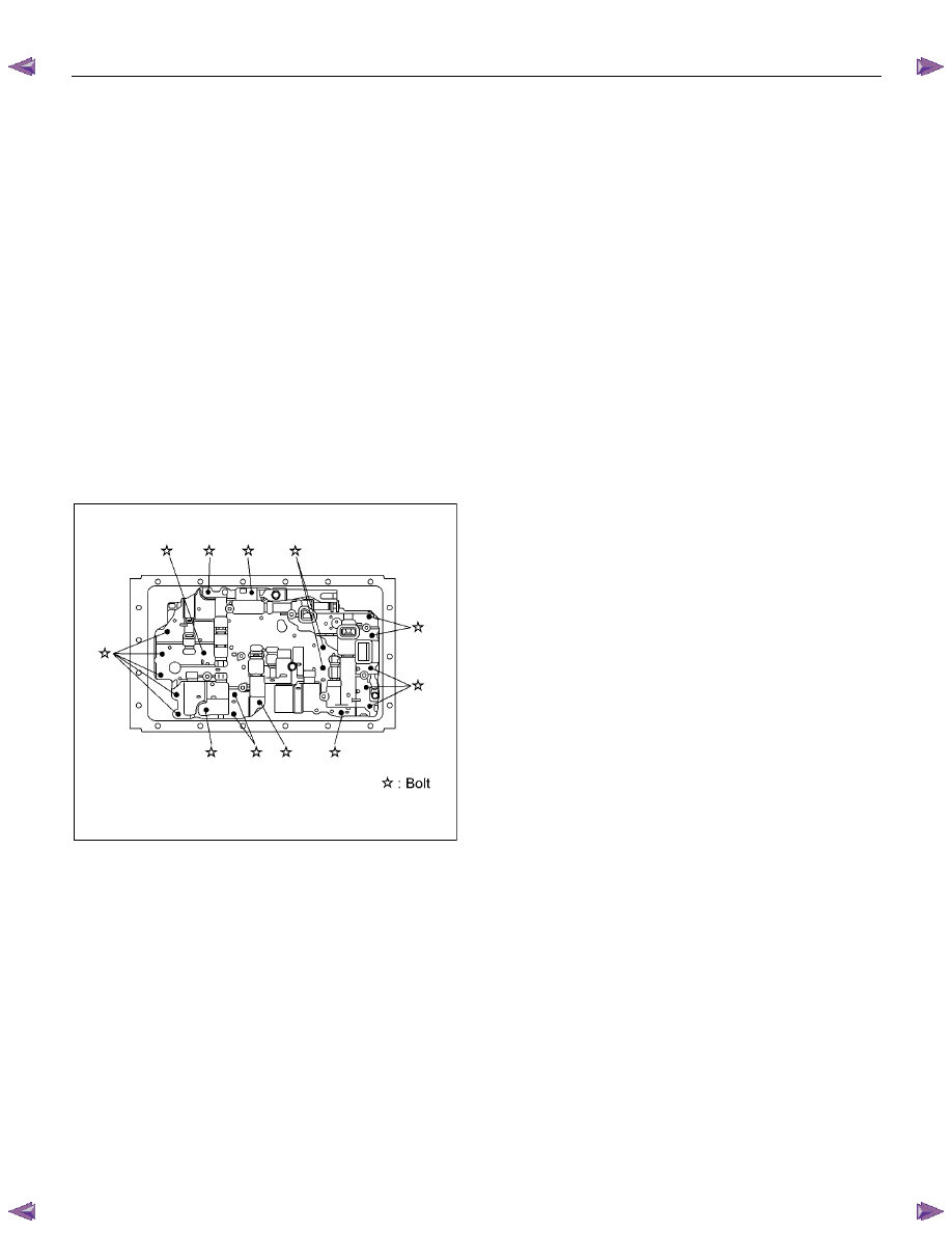
3. Valve body fixing bolts
Each bolt location is indicated in the figure.
Torque : 10 N
⋅⋅⋅⋅m (1.0 kgf⋅⋅⋅⋅m/87 Ib⋅⋅⋅⋅in)
NOTE: Tighten the bolts toward outside equally.
244R200078
4. Oil strainer fixing bolts
Torque : 10 N
⋅⋅⋅⋅m (1.0 kgf⋅⋅⋅⋅m/87 Ib⋅⋅⋅⋅in)
5. Oil pan fixing bolts
Torque : 7.4 N
⋅⋅⋅⋅m (0.75 kgf⋅⋅⋅⋅m/65 Ib⋅⋅⋅⋅in)
ON-VEHICLE SERVICE (AW30–40LE) 7A3-37
Rear Oil Seal (Adapter Housing, 4
××××
4)
Removal
1. Remove the front and rear propeller shaft assembly
from the transfer case.
2.
Remove the transfer case assembly from the
transmission case.
Refer to Section 7D TRANSFER.
3. Using a screwdriver, remove the rear oil seal.
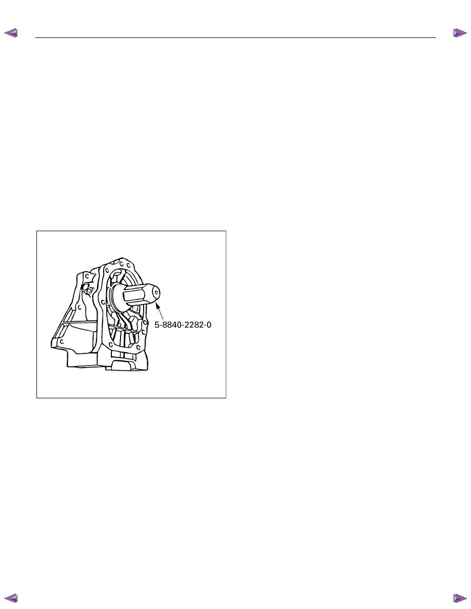
Installation
1. Apply ATF to a new rear oil seal lip.
2. Using oil seal installer, install the rear oil seal to the
adapter housing.
Oil seal installer : 5-8840-2282-0
240RY00003
3. Install the transfer case assembly.
Refer to section 7D TRANSFER.
4. Install the front and rear propeller shaft assembly.
Torque (Propeller shaft flange bolt) :
63 N
⋅⋅⋅⋅m (6.4 kgf⋅⋅⋅⋅m/46 Ib⋅⋅⋅⋅ft)
7A3-38 ON-VEHICLE SERVICE (AW30–40LE)
Rear Oil Seal (Extension Housing, 4
××××
2)
Removal
1. Remove the rear propeller shaft assembly.
2. Using a screwdriver, remove the rear oil seal.
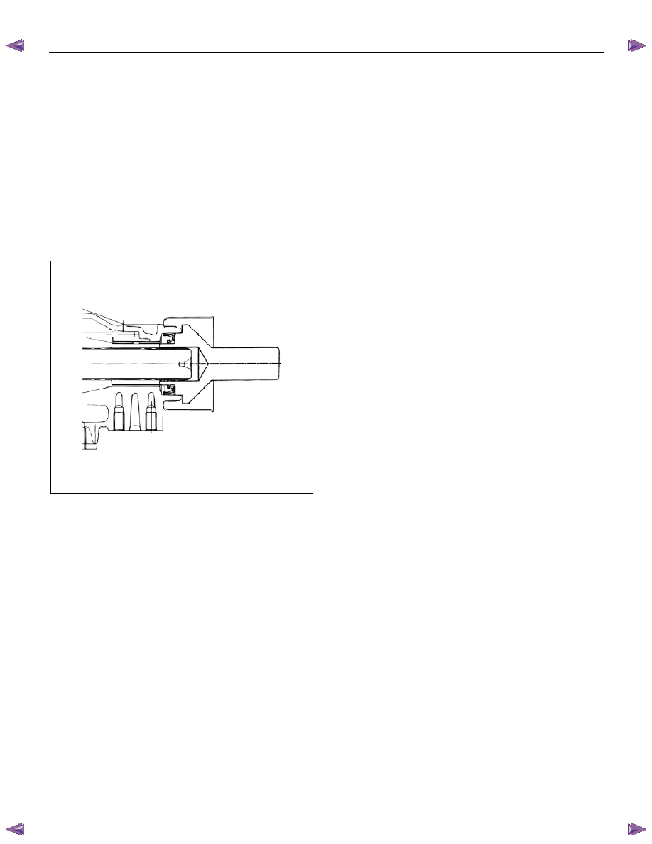
Installation
1. Apply ATF to a new rear oil seal lip.
2. Using oil seal installer, install the rear oil seal to the
extension housing.
Oil seal installer : 5-8840-2702-0
249L100005
3. Install the rear propeller shaft.
Torque (Flange bolt): 63 N
⋅⋅⋅⋅m (6.4 kgf⋅⋅⋅⋅m/46 Ib⋅ft)
Нет комментариевНе стесняйтесь поделиться с нами вашим ценным мнением.
Текст