Isuzu KB P190. Manual — part 1029
ON-VEHICLE SERVICE (AW30–40LE) 7A3-31
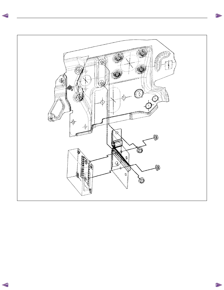
Transmission Control Module (TCM)
RTW37ALF001801
Removal
Preparation:
Disconnect negative (–) battery cable.
1. Disconnect the TCM harness connectors.
2.
Remove fixing nuts (2 pieces) and TCM with
bracket from the car.
NOTE: The TCM is fitted under instrument panel of the
driver's compartment by means of two stud bolts.
3. Remove fixing nuts (2 pieces) and remove TCM
from bracket.
Installation
To install, follow the removal steps in reverse order.
7A3-32 ON-VEHICLE SERVICE (AW30–40LE)
Shift Solenoid and Lock-Up Solenoid
Removal
Preparation:
• Disconnect negative (–) battery cable.
• Drain the fluid.
Refer to ATF REPLACEMENT in this section.
1. Remove oil lever gage and oil filler tube.
2. Support transfer case (4
×
4) or rear cover (4
×
2)
with a transmission jack.
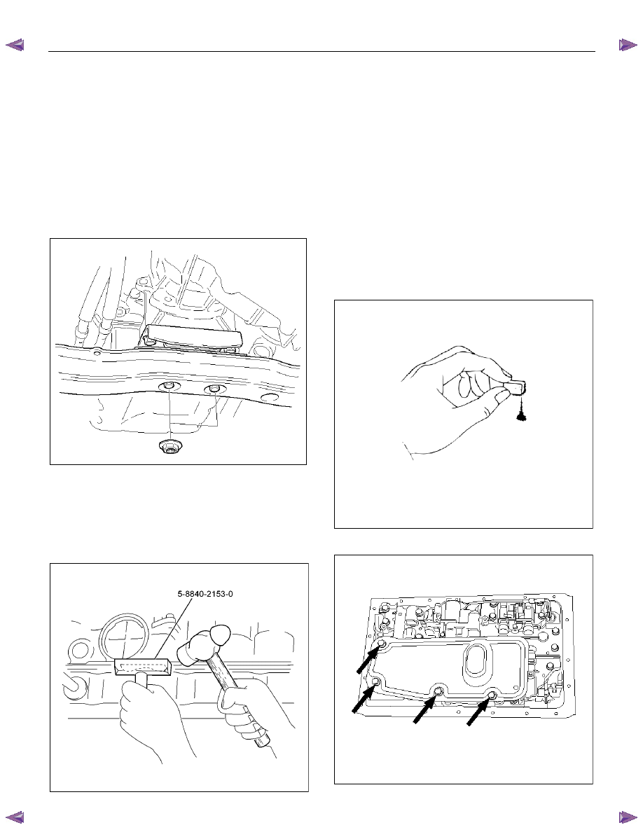
3. Remove engine rear mounting nuts.
F07RW008
4. Remove fule pipe heat protector on tansmission
corssmenber.
5. Remove fuel pipe from the crossmenber.
6. Remove transmission crossmenber.
7. Remove the nineteen bolts.
8. Remove oil pan, using seal cutter 5-8840-2153-0.
RUW37ASH002901
NOTE: Do not turn over the transmission as this will
contaminate the valve body with foreign materials in the
bottom of the oil pan.
Remove oil pan by lifting the transmission case.
Oil pan seal cutter: 5-8840-2153-0
Examine particles in oil pan
Remove the magnet and use it to collect any steel
chips.
Look carefully at the chips and particles in the oil
pan and on the magnet to anticipate what type of
wear you will find in the transmission:
Steel (magnetic) . . . . .. bearing,
gear
and
clutch plate wear
Brass (non-magnetic). . .. bushing wear
240RY00008
9. Remove the oil strainer assembly.
244RY00003
ON-VEHICLE SERVICE (AW30–40LE) 7A3-33
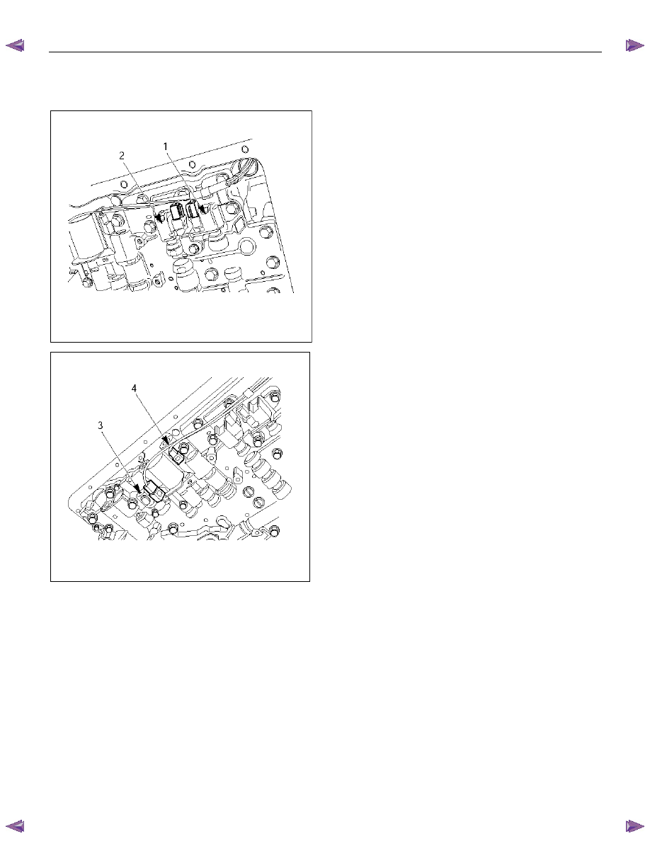
10.Disconnect the solenoid wiring connectors from the
shift solenoid S1(1), S2(2), lock-up solenoid(3) and
pressure control solenoid(4).
249RY00011
249RY00012
11. Remove each retaining bolts and solenoids. (Except
pressure control solenoid:)
Pressure control solenoid cannot be removed.
Installation
To install, follow the removal steps in reverse order
noting the following point;
Refer to the section Reassembly of Major
Components(2) and Transmission Removal and
Installation.
Torque:
Solenoid S1, S2 bolt – 7 N
⋅m (0.7 kgf⋅⋅⋅⋅m/61 Ib⋅in)
Lock-up solenoid bolt – 10 N
⋅m (1.0 kgf⋅⋅⋅⋅m/87
Ib
⋅in)
7A3-34 ON-VEHICLE SERVICE (AW30–40LE)
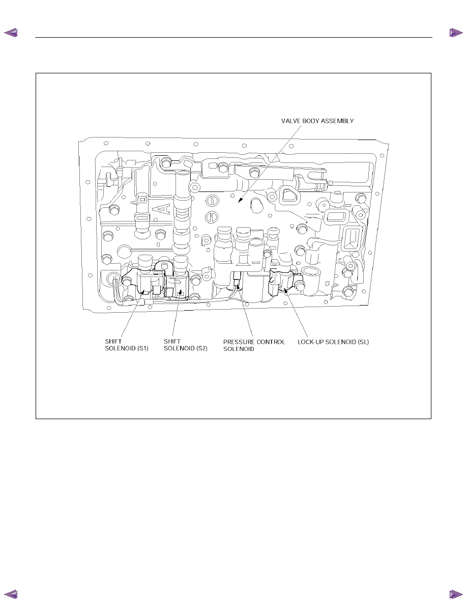
Valve Body Assembly and Pressure Control Solenoid
244RY00009
Removal
Preparation:
• Disconnect negative (–) battery cable.
• Drain the fluid.
Refer to ATF REPLACEMENT in this section.
1. Remove the nineteen bolts and oil pan.
Нет комментариевНе стесняйтесь поделиться с нами вашим ценным мнением.
Текст