Isuzu KB P190. Manual — part 139
4C1-52 FRONT WHEEL DRIVE
Preload Adjustment
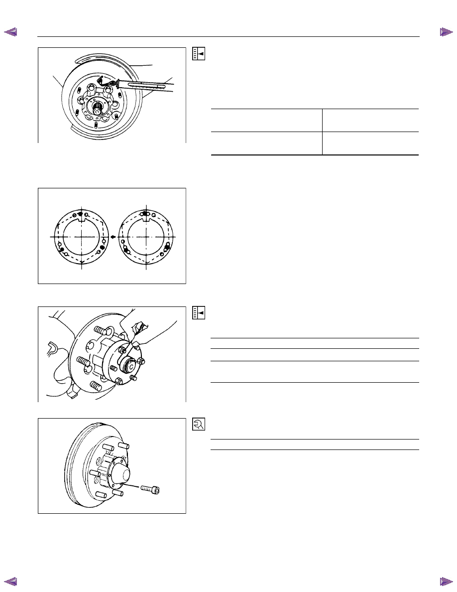
Tighten the hub nut at 29.4 N
⋅m (3 kgf⋅m / 21.7 lb·ft), then
loosen the nut to the full.
Tighten the hub nut at the value given below, using a spring
scale on the wheel pin.
Bearing Preload
N (kgf/lb)
New bearing and New oil seal
22 - 27
(2.2 - 2.8 / 4.9 - 6.2)
Used bearing and New oil seal
14 - 20
(
1.4 - 2.0 / 3.1 - 4.5)
If the measured bearing preload is outside the specifications,
adjust it by loosening or tightening the bearing nut.
9. Lock Washer
Turn the side with larger diameter of the tapered bore to the
vehicle outer side, and attach the washer.
If the bolt holes in the lock plate are not aligned with the
corresponding holes in the nut, reverse the lock plate.
If the bolt holes are still out of alignment, turn in the nut just
enough to obtain alignment,. Screw is to be fastened tightly so
its head may come lower than the surface of the washer.
10. Flange (4×4 model only)
Apply adhesive (LOCTITE 5
15 or equivalent) to both joining
flange faces then install hub flange.
11. Snap ring, shims (4×4 model only)
Adjust the clearance between the flange and the snap ring.
Clearance mm(in)
0 - 0.2 (0 - 0.008)
Adjust shims available
mm(in)
0.2, 0.3, 0.5,
1.0
(0.008, 0.0
12, 0.020, 0.039)
RTW440SH00090
1
13. Bolt
Torque N
⋅m (kgf⋅m/lb⋅ft)
59 (6.0 / 43)
• Refer to SECTION 3E “WHEELS AND TIRES” for wheel
install procedure.
FRONT WHEEL DRIVE 4C1-53
FRONT HUB AND DISC
(4
××××4 Manual Locking Hub Model)
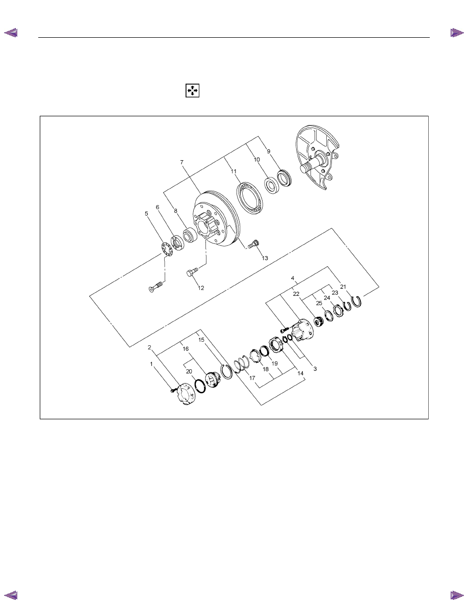
DISASSEMBLY
Refer to SECTION 3E “WHEELS AND TIRES” for wheel removal procedure
RTW440LF00030
1
Disassembly Steps
▲ 1. Bolt
2. Cover assembly
3. Snap ring and shim
4. Body assembly
5. Lock washer
▲ 6. Hub nut
▲ 7. Hub and disc assembly
8. Outer bearing
9. Oil seal
10. Inner bearing
11. ABS sensor rotor
▲ 12. Bolt
▲ 13. Wheel pin
▲ 14. Clutch assembly
15. Snap ring
16. Knob
17. Compression spring
18. Follower
▲ 19. Retaining spring
20.
X-ring
2
1. Snap ring
22. Inner assembly
23. Snap ring
24.
Ring
25.
Spacer
4C1-54 FRONT WHEEL DRIVE
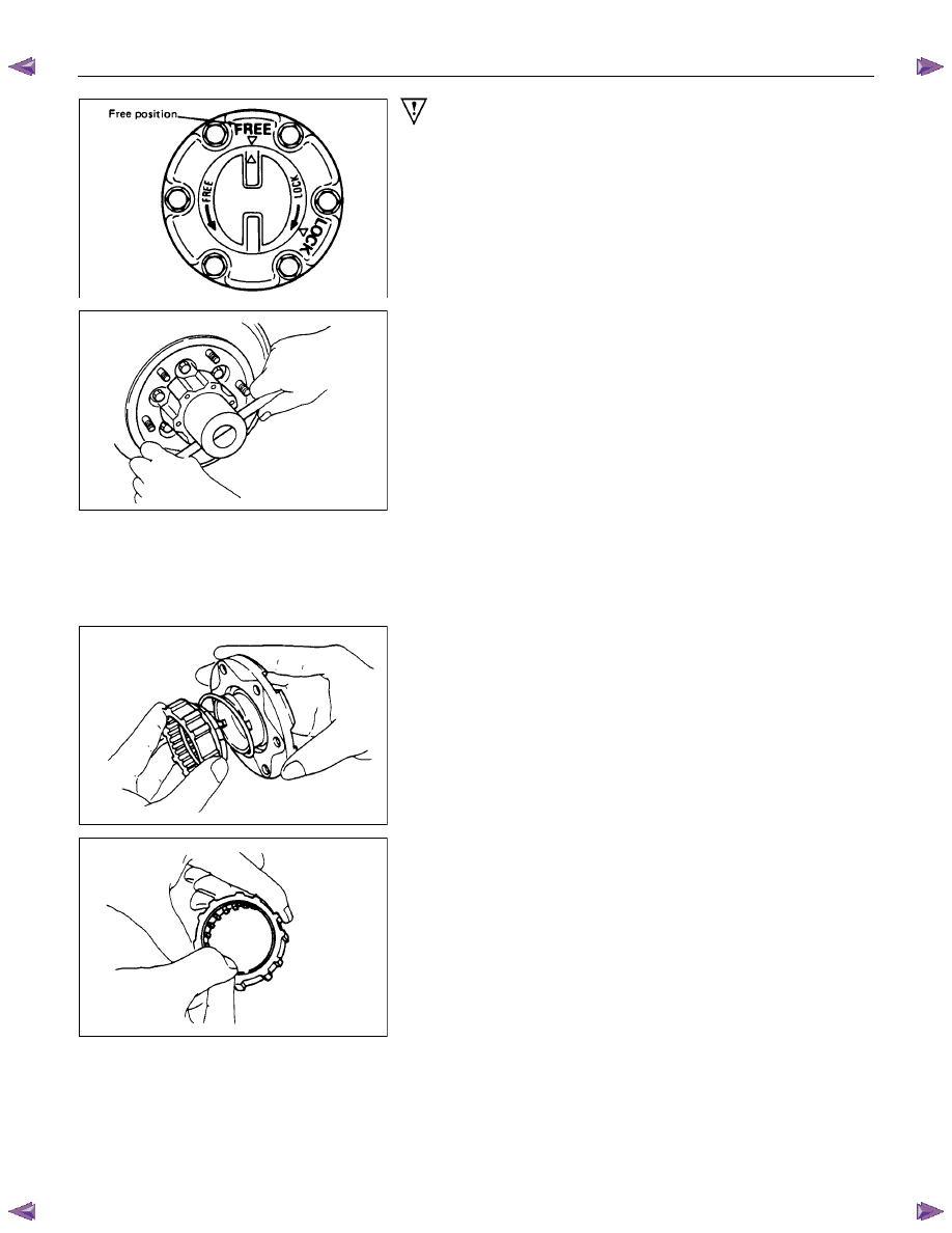
Important Operations
1. Bolt
Before removal, shift transfer lever into “2H” position and set
free wheeling hub knob into “FREE” position.
6. Hub nut
Wrench : 5-8840-2
117-0
7. Hub and disc assembly
Before disassembly, remove the disc brake caliper assembly
and hang it on the frame with wires.
Refer to Section “Brake” for disc brake caliper removal
procedure.
14. Clutch Assembly
While pushing follower knob, turn clutch assembly clockwise
and then remove clutch assembly from knob.
19. Retaining Spring
Remove retaining spring from clutch assembly by turning it
counterclockwise.
FRONT WHEEL DRIVE 4C1-55
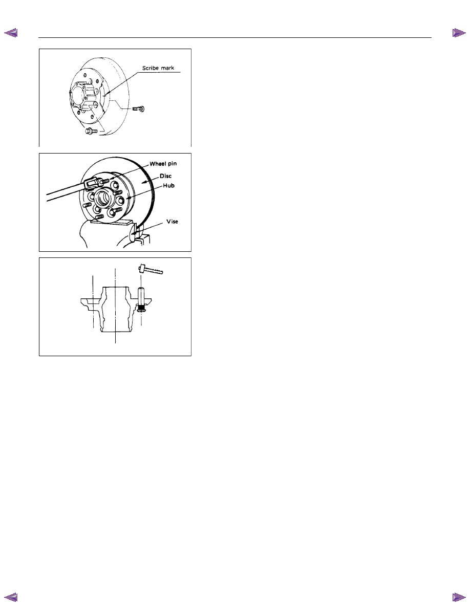
12. Bolt
13. Wheel Pin ; Front Hub
(
1) Scribe mark on hub to disc before disassembly to insure
proper assembly.
(2) Drive out the ABS sensor rotor using a metal bar and
hammer through the two bolt holes.
• Discard the used ABS sensor rotor
Refer to the section Brake.
(3) Clamp hub and disc assembly in vise using protective pads
and remove six (6) disc to hub retaining bolts.
(4) Place hub on a suitable work surface and remove wheel
studs, as required, using a hammer.
Нет комментариевНе стесняйтесь поделиться с нами вашим ценным мнением.
Текст