Isuzu KB P190. Manual — part 137
4C1-44 FRONT WHEEL DRIVE
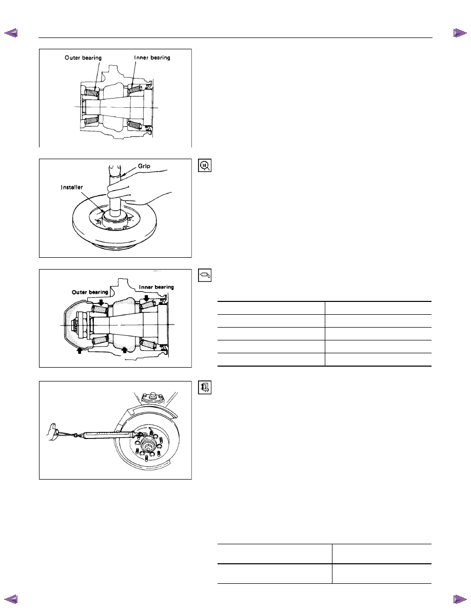
(2) Install the outer and inner bearing into the hub with fingers.
(3) Install oil seal using special tools.
Discard the used oil seal and install a new one.
Installer : 5-8840-2853-0
Grip :
5-8840-0007-0
Hub cap
Hub
6. Hub and Disc Assembly
12. Hub Cap
Apply grease in the hub and hub cap.
Description Amount
g(oz)
Hub 50
(1.77)
Hub cap
20 (0.71)
Outer bearing
6.5 (0.23)
Inner bearing
12 (0.42)
9. Hub nut
Adjustment of front wheel hub bearing preload
1. Tighten spindle nut to 29 N
⋅m (3.0 kgf·m/22 lb⋅ft) torque.
2. Turn the hub 2-3 turns and loosen the nut just enough so
that it can be turned with the fingers.
3. Turn the nut all the way in with the fingers and check to be
sure the hub has no free play.
4. Measure the bearing preload by pulling one of the wheel
hub studs with a spring scale.
5. Tighten the spindle nut until specified bearing preload Is
obtained.
6. Install the split pin in the nut retainer.
Discard the used split pin and install a new one.
After reassembling, install the disc brake caliper assembly.
Bearing Preload
N (kgf/lb)
New bearing and New oil seal
9.3 - 13.3
(0.95 - 1.36 / 2.09 – 3.00)
Reuse bearing and New oil seal
9.3 - 13.3
(0.95 - 1.36 / 2.09 – 3.00)
FRONT WHEEL DRIVE 4C1-45
RTW74CSH000101
14.Bolt
Torque N
⋅m (kgf⋅m/lb⋅ft)
226 (23.0/166)
• Refer to SECTION 3E “WHEELS AND TIRES” for install
procedure.
4C1-46 FRONT WHEEL DRIVE
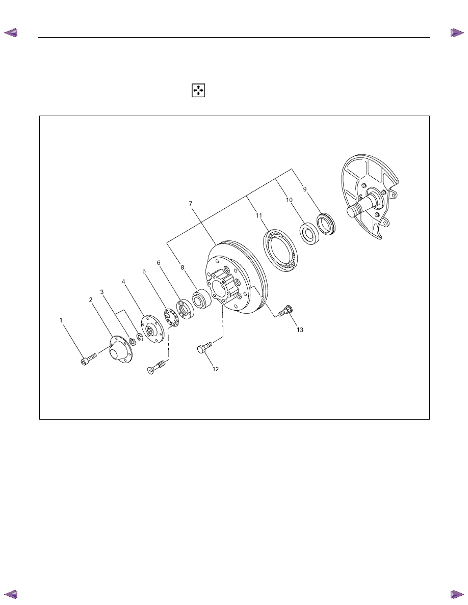
FRONT HUB AND DISC
(4×4, 4×2 High Ride Suspension, 4×4 Rigid Hub, 4×4 Shift On the Fly Model)
Disassembly
Refer to SECTION 3E “WHEELS AND TIRES” for wheel removal procedure
411R300011
Disassembly Steps
1.
Bolt
2.
Hub
cap
3. Snap ring and shim (4×4 model only)
4. Flange (4×4 model only)
5.
Lock
washer
▲ 6. Hub nut
▲ 7. Hub and disc assembly
8.
Outer
bearing
9.
Oil
seal
10.
Inner
bearing
11. ABS sensor rotor
▲12. Bolt
▲13. Wheel pin
FRONT WHEEL DRIVE 4C1-47
Important Operations
6. Hub nut
Wrench : 5-8840-2117-0
7. Hub and disc assembly
Before disassembly, remove the disc brake caliper assembly
and hang it on the frame with wires.
Refer to Section “Brake” for disc brake caliper removal
procedure.
12. Bolt
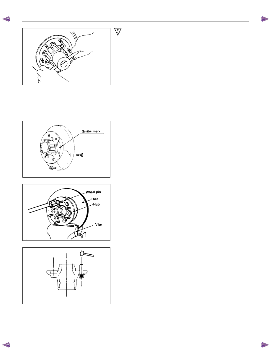
13. Wheel Pin ; Front Hub
(1) Scribe mark on hub to disc before disassembly to insure
proper assembly.
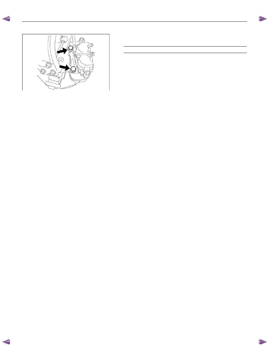
(2) Drive out the ABS sensor rotor using a metal bar and
hammer through the two bolt holes.
• Discard the used ABS sensor rotor
Refer to the section Brake.
(3) Clamp hub and disc assembly in vise using protective pads
and remove six (6) disc to hub retaining bolts.
(4) Place hub on a suitable work surface and remove wheel
studs, as required, using a hammer.
Нет комментариевНе стесняйтесь поделиться с нами вашим ценным мнением.
Текст