Isuzu KB P190. Manual — part 1158
7B1-26 MANUAL TRANSMISSION
Disassembly
1. Use a pair of snap ring pliers to remove the bearing
snap ring.
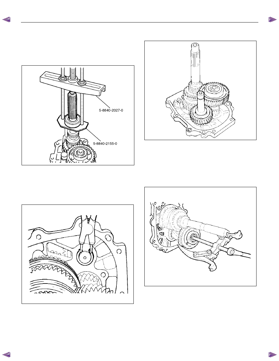
2. Set the bearing remover 5-8840-2155-0 and the
puller 5-8840-2027-0 to the bearing
and the
mainshaft end, to remove the ball bearing.
262L100001
3. Remove the bearing snap ring, clip, speedometer
drive gear, retainer snap ring and the retainer.
4. Remove the thrust plate, thrust washer and lock
ball.
5. Use a pair of snap ring pliers to remove the reverse
idler gear snap ring.
226RS004
6. Remove the reverse idler gear assembly from the
intermediate plate.
226RS005
7. Remove the idle shaft pin, thrust washer, reverse
idler gear, and reverse idler shaft.
8. Use a pair of snap ring pliers to remove the snap
ring.
9. Attach a universal puller to the counter gear shaft.
Use a universal puller to remove the ball bearing
and the counter 5th gear.
226RS006
10. Remove the counter reverse gear.
MANUAL TRANSMISSION 7B1-27
11. Remove the 5th gear, 5th block ring, and needle
bearing (2 piece type).
226RS007
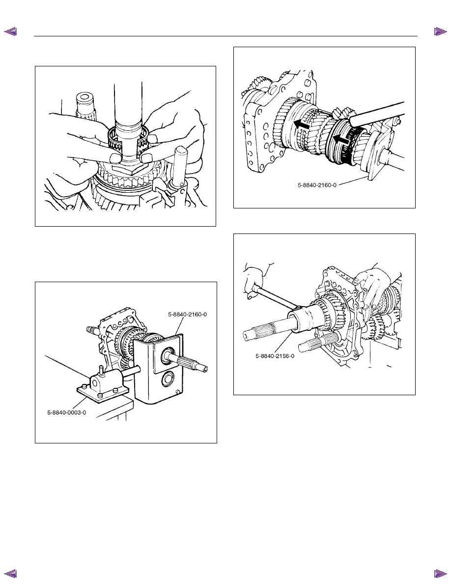
12. Remove the mainshaft nut according to following
steps.
Attach the holding fixture 5-8840-2160-0 and the
base 5-8840-0003-0 to the mainshaft and the
counter gear.
226RW212
• Engage the 3rd-4th synchronizer with the 3rd
gear.
• Engage the 1st-2nd synchronizer with the 1st
gear.
226RW210
• Use the mainshaft nut wrench 5-8840-2156-0 to
remove the mainshaft nut.
226RW211
7B1-28 MANUAL TRANSMISSION
13. Use screw drivers between the reverse gear and the
bearing plate to remove the Rev-5th synchronizer
assembly, together with the reverse block ring and
reverse gear.
226RS010
14. Remove the needle bearing.
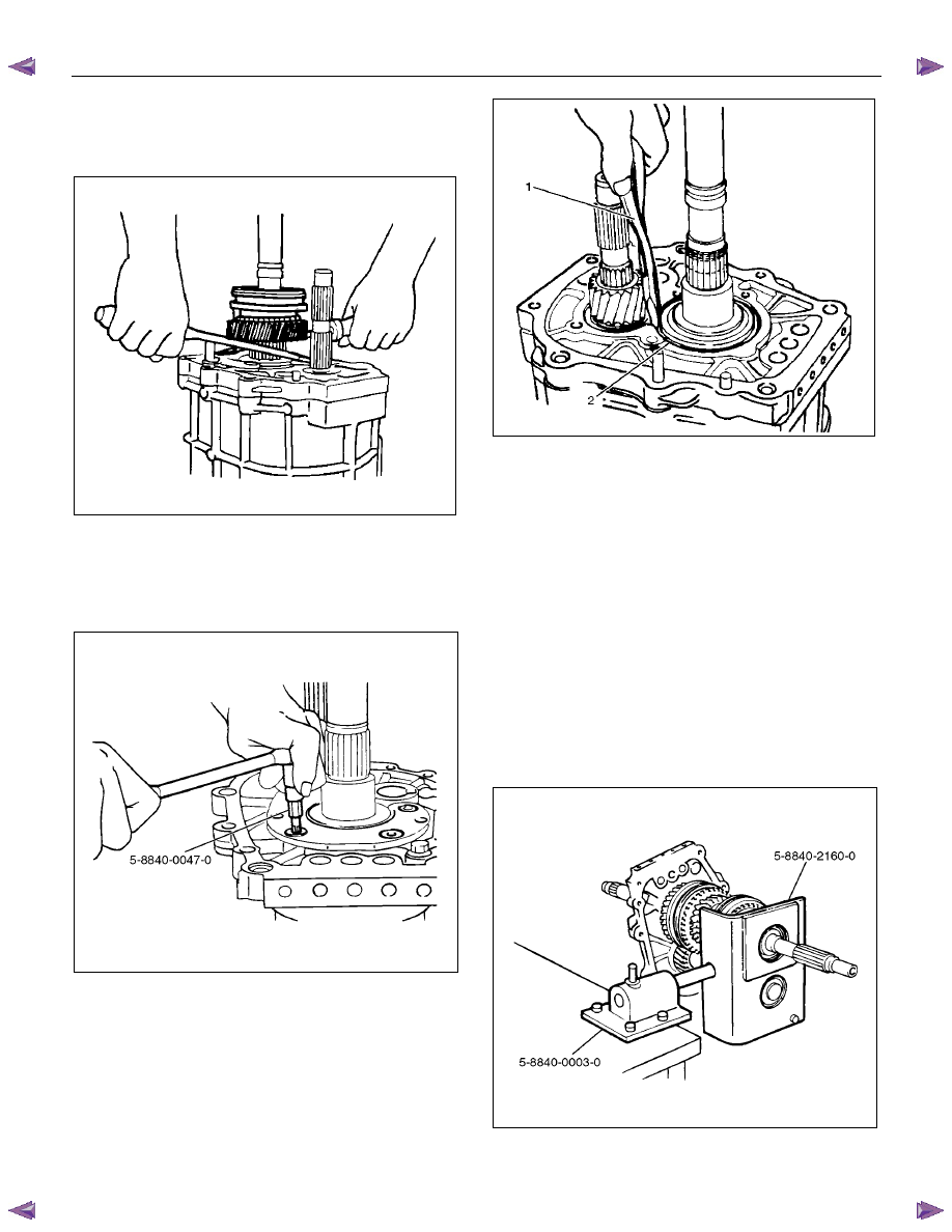
15. Use the torx bit wrench (T- 45) 5-8840-0047-0 to
remove the bearing plate and screw from the
intermediate plate.
220RW137
16. Use the snap ring pliers (1) to remove the mainshaft
bearing snap ring (2).
226RS011
17. Hold the snap ring open with the pliers.
Push the intermediate plate toward the rear of the
transmission to remove it.
The bearing snap ring will come free.
Inspection and Repair
Refer to Top Gear Shaft, Main Gear Shaft, and Counter
Gear in this section for inspection and repair.
Reassembly
1. Mesh the counter gear with the mainshaft assembly.
Set the holding fixture 5-8840-2160-0 to the
mainshaft and the counter gear, and then install it on
the base 5-8840-0003-0.
Install the intermediate plate on the gear assembly.
226RW212

MANUAL TRANSMISSION 7B1-29
2. Install the bearing snap ring.
3. Apply the recommended thread locking agents
(LOCTITE 242) or its equivalent to each of the
bearing plate screw threads.
Install the bearing plate and screw.
Tighten the screws to the specified torque by using
torx bit wrench (T- 45) 5-8840-0047-0.
Torque: 15 N
⋅⋅⋅⋅m (1.5 kgf⋅⋅⋅⋅m/11 lb⋅⋅⋅⋅ft)
220RW137
4. Install the needle bearing, reverse gear, and reverse
block ring.
5.
Assemble rev-5th synchronizer assembly by
performing the following steps.
1. Turn the clutch hub face (1) toward the sleeve
groove (2) (rear side) on the outer
circumference.
2. Check that the inserts (3) fit snugly into the
clutch hub (5) ring insert grooves.
3. Check that the inserts springs (4) are fitted to
the inserts as shown in the illustration.
4. Check that the clutch hub (5) and the sleeve (6)
slide smoothly.
5. Install the synchronizer assembly to the
mainshaft.
The clutch hub face with the heavy boss must be
facing the reverse gear side.
226RS013
226RS049
Нет комментариевНе стесняйтесь поделиться с нами вашим ценным мнением.
Текст