Isuzu KB P190. Manual — part 710

Engine Mechanical – V6
Page 6A1–63
Page 6A1–63
Step Action
Yes
No
8
Tighten any loose fasteners to the correct torque specification, refer to
6 Torque Wrench Specifications.
Replace any incorrect or missing fasteners.
Does the drive belt continue to fall off?
Go to Step 9
Go to Step 12
9
Test the accessory drive belt tensioner for correct operation, refer to
Accessory Drive Belt Tensioner Diagnosis in this Section.
Did you accessory drive belt tensioner operate correctly?
Go to Step 11
Go to Step 10
10 Replace the drive belt tensioner, refer to
3.7 Accessory Drive Belt Tensioner Assembly.
Does the drive belt continue to fall off?
Go to Step 11
Go to Step 12
11 Inspect for a failed drive belt idler and drive belt tensioner bearings.
Did you find and repair any failed bearings?
Go to Step 12
Refer to Diagnostic
Aids in this Section
12 If required, reinstall the accessory drive belt and operate the system to
confirm the repair.
Does the drive belt continue to fall off?
Go to Step 2
Accessory drive
system OK

Engine Mechanical – V6
Page 6A1–64
Page 6A1–64
Drive Belt Excessive Wear
Definition
Excessive wear can be defined as wear at the outside ribs of the drive belt (frayed edges), usually caused by an
incorrectly installed drive belt
Diagnostic Aids
Excessive wear of a drive belt is usually caused by an incorrect installation or an incorrect drive belt fitted. Minor pulley
misalignment will not cause excessive wear, but will cause the drive belt to fall off. Major pulley misalignment may cause
excessive wear, but would also result in the drive belt falling off.
Test Description
The numbers below refer to steps in the diagnostic table.
2
Confirms the drive belt is correctly installed onto all of the accessory drive system pulleys. Wear on the drive belt
may be caused by incorrectly positioning the drive belt by one or more grooves to a particular pulley.
3
The installation of the drive belt that is the incorrect width will cause wear on the drive belt. The drive belt ribs
should match all the grooves on all the pulleys in the accessory drive system.
4
Confirms the drive belt is not contacting any parts of the engine or body while the engine is running. There should
be sufficient clearance when the accessory drive component loads varies. The drive belt should not come into
contact with any engine or body parts.
Diagnostic Table
Step Action
Yes
No
1
Did you review the information provided in 2.2 Symptoms, and
perform the required inspections.
Go to Step 2
Go to
2.2 Symptoms
2
Inspect the accessory drive belt for correct installation.
Is the drive belt installed correctly?
Go to Step 5
Go to Step 3
3
Ensure that the drive belt is the correct one for the application.
Is the correct drive belt installed?
Go to Step 5
Go to Step 4
4
Is the drive belt contacting any engine or body components with the
engine running?
Go to Step 6
Refer to Diagnostic
Aids in this Section
5
Install a new accessory drive belt, refer to 3.5 Accessory Drive Belt.
Did you replace the accessory drive belt?
Go to Step 6
—
6
If required, reinstall the accessory drive belt and operate the system to
confirm the repair.
Did you correct the excessive wear?
Accessory drive
system OK
Go to Step 2

Engine Mechanical – V6
Page 6A1–65
Page 6A1–65
Accessory Drive Belt Tensioner Diagnosis
Diagnostic Table
Step Action
Yes
No
1
1
Remove the accessory drive belt.
2
Inspect the drive belt tensioner pulley.
Is the drive belt tensioner pulley loose or misaligned?
Go to Step 4
Go to Step 2
2
Rotate the drive belt tensioner.
Does the drive belt tensioner rotate freely, without any unusual
resistance or binding?
Go to Step 3
Go to Step 4
3
1
Using a suitable torque wrench, measure the torque required to
lift the drive belt tensioner off the stop.
2
Using a known good tensioner, measure the torque required to
lift the drive belt tensioner off the stop.
Is the first torque reading within 10% of the second reading?
Accessory drive belt
tensioner OK
Go to Step 4
4
Replace the drive belt tensioner, refer to
3.7 Accessory Drive Belt Tensioner Assembly.
Is the repair complete?
Accessory drive belt
tensioner OK
—
Engine Mechanical – V6
Page 6A1–66
Page 6A1–66
3
Minor Service Operations
A T T E N T I O N
The V6 engine is a combination of numerous components, containing machined, honed, polished and lapped
surfaces manufactured on the latest, high technology production equipment. Many of the components
contain tolerances measured in thousandths of a millimetre. Consequently, when any engine component is to
be serviced, care and cleanliness are extremely important.
Prior to re-assembly of the engine, all components must be cleaned and inspected in accordance with the
relevant clean and inspect procedures throughout this Section, and replaced or repaired where required.
In addition to cleaning and inspecting components, a liberal coating of engine oil should be applied to friction
surfaces during assembly to protect and lubricate the surfaces on initial operation.
When performing any service operation, it should be understood that correct cleaning and protection of
machined surfaces and friction areas is part of the repair procedure. This is considered standard workshop
practice, even if not specifically stated. Torque values must be used as specified during reassembly to
ensure correct retention of all components.
Through out this section, fastener torque wrench specifications may be accompanied with the following
identification marks:
■
Fasteners must be replaced after loosening.
Fasteners either have micro encapsulated sealant applied or incorporate a mechanical thread lock and
should only be re-used once. If in doubt, replacement is recommended.
If one of these identification marks is present alongside a fastener torque wrench specification, the
recommendation regarding that fastener must be adhered to.
3.1 Engine
Oil
The procedure outlined below is typically the same for both rear wheel drive and all wheel drive vehicles.
Check
The following procedure is applicable to both rear wheel and all wheel drive vehicles
1
Run the engine to bring it to normal operating temperature.
2
Park the vehicle on a level surface. A vehicle that is not level will affect the accuracy of the level reading.
3
Stop the engine and wait 5 to 10 minutes to allow the oil to drain back into the oil pan.
4
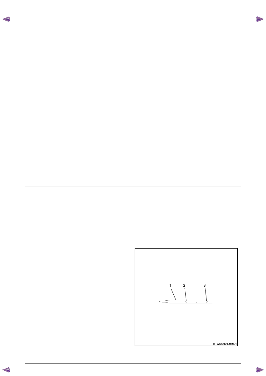
Remove the oil level indicator (1) and wipe clean.
5
Insert the indicator, ensuring it is fully seated.
6
Slowly remove the indicator to avoid smearing. Hold it
horizontally or with lower end slightly down to avoid
oil running along indicator.
7
Observe the oil level where it passes over the centre
line of the indicator.
8
If the level is lower than the Add mark (2), add
enough oil to the engine to reach the Upper mark (3).
Do not add too much oil as the reading should never
be above the Upper mark.
N O T E
When topping up the oil, allow approximately 5
to 10 minutes for the added oil to fully drain into
the oil pan.
Figure 6A1 – 23
Нет комментариевНе стесняйтесь поделиться с нами вашим ценным мнением.
Текст