Isuzu KB P190. Manual — part 717
Engine Mechanical – V6
Page 6A1–91
Page 6A1–91
3.11 Exhaust Manifold Assembly
Remove
Allow the engine to cool before commencing.
Disconnection of the battery affects
certain vehicle electronic systems, refer to
1.1 WARNING, CAUTION and NOTES
before
disconnecting the battery.
1
Disconnect the battery negative terminal.
2
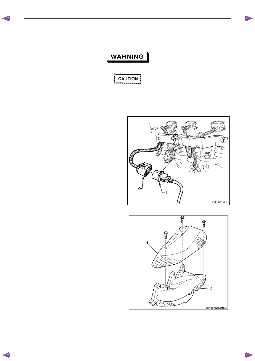
Remove the oxygen sensor harness connector (1)
from the retaining bracket.
3
Disconnect the oxygen sensor wiring harness
connector from the engine wiring harness connector
(2).
4
Unclip the oxygen sensor wiring harness retaining clip
and move aside.
5
For the left-hand side:
Remove the oil level indicator tube.
6
Raise the front of the vehicle and place on stands,
refer to
Section 0A General Information
.
7
Working from under the vehicle, remove the two
exhaust manifold to exhaust pipe flange nuts, refer to
Section 6F Exhaust System - V6
.
Figure 6A1 – 56
8
Remove the three bolts attaching the exhaust
manifold outer heat shield (1) to the exhaust manifold
(2).
Figure 6A1 – 57
Engine Mechanical – V6
Page 6A1–92
Page 6A1–92
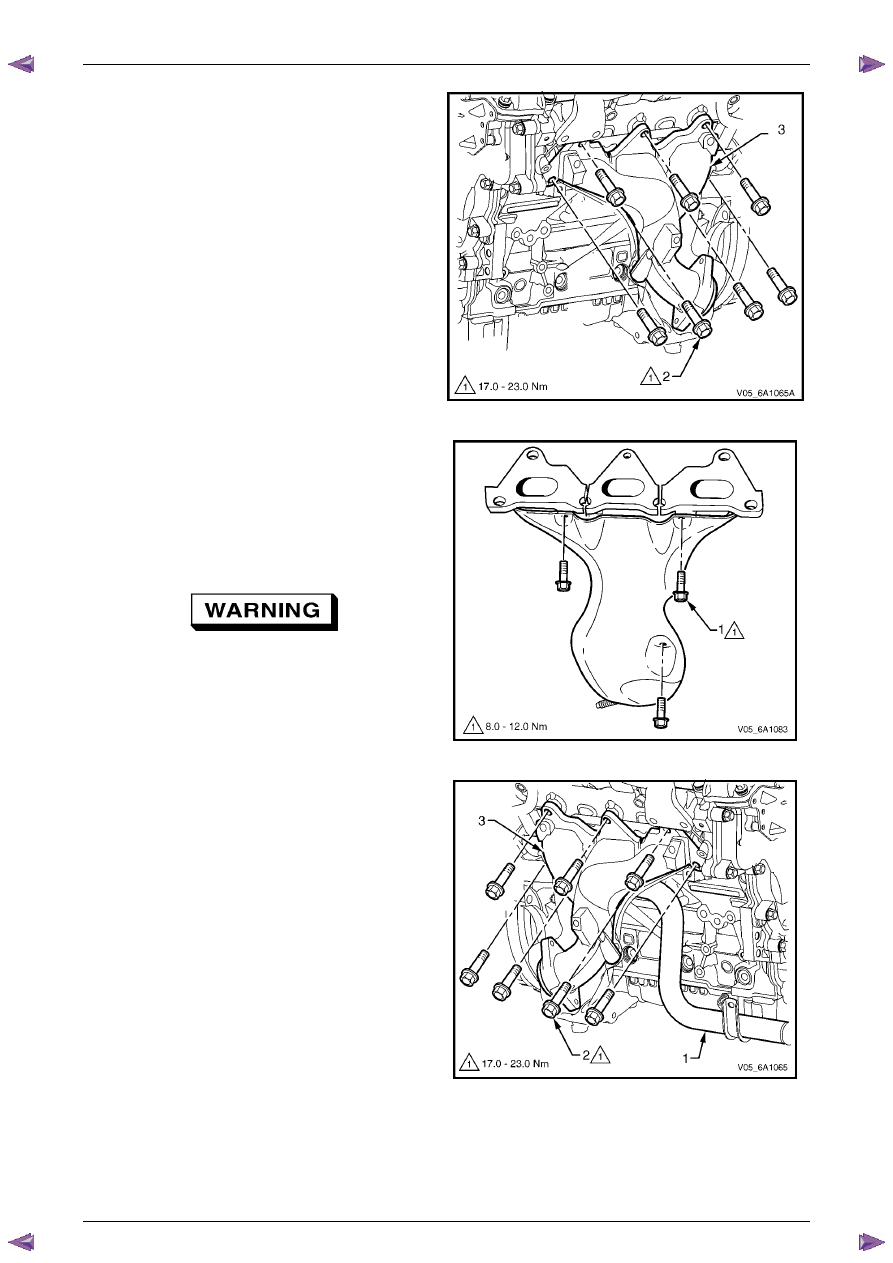
9
Progressively loosen the seven exhaust manifold
attaching bolts (2), working from the outside to the
centre and then remove the bolts.
10
Manoeuvre the exhaust manifold (3), away from the
cylinder head.
11
Remove and discard the exhaust manifold to cylinder
head gasket.
Figure 6A1 – 58
12
Remove the three bolts (1), attaching the exhaust
manifold inner heat shield to the exhaust manifold.
13
Using a suitable commercially available non-corrosive
cleaning solvent and a soft bristled parts cleaning
brush, thoroughly clean the exhaust manifold.
14
Dry the exhaust manifold using compressed air.
Safety glasses must be worn when using
compressed air.
Figure 6A1 – 59
N O T E
• The same procedure applies to the Right-
hand exhaust manifold.
• To gain access to the lower rear exhaust
manifold attaching bolts (2), apply a slight
downward movement to the coolant inlet
pipe (1).
Engine Mechanical – V6
Page 6A1–93
Page 6A1–93
Inspect
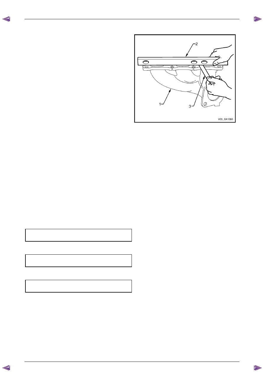
Inspect the exhaust manifold (1) for the following:
•
Damage to the threaded holes for the heat shield
mounting.
•
Damage to the exhaust manifold mounting holes.
•
Damage to the threads of the exhaust manifold to
exhaust pipe flange studs.
•
Damage to the gasket sealing surfaces.
•
Using a straight edge (2) and feeler gauges (3), check
the cylinder head mounting face of the exhaust
manifold does not exceed the maximum distortion
specification of 0.25mm.
N O T E
If the surface flatness is not within
specifications, the exhaust manifold is warped
and must be replaced.
Figure 6A1 – 60
Reinstall
Reinstallation of the exhaust manifold assembly is the reverse of the removal procedure, noting the following:
1
Ensure the exhaust manifold, cylinder head and exhaust pipe flange surfaces are clean.
2
Position a new exhaust manifold gasket onto the exhaust manifold.
3
Apply a 5 mm bead of Loctite 272 thread sealant (or equivalent) to the threads of the exhaust manifold attaching
bolts.
4
Install the bolts into the exhaust manifold. This will prevent the gasket from falling off the manifold.
5
Manoeuvre the exhaust manifold into position and install the exhaust manifold attaching bolts.
6
From underneath the vehicle install the exhaust manifold to exhaust pipe flange nuts.
7
Tighten the exhaust manifold attaching bolts to the correct torque specification.
N O T E
When tightening the exhaust manifold to cylinder
head attaching bolts, begin with the centre bolts,
then alternate from side to side to the outer bolts.
Exhaust manifold to cylinder head
attaching bolt torque specification. . ...17.0 – 23.0 Nm
8
Apply an anti seize compound such as Caltex Kopr-Kote (or equivalent) to the cleaned heat shield bolt threads.
Install the heat shield attaching bolts and tighten to the correct torque specification.
Exhaust manifold heat shield attaching
bolt torque specification . . . . . . . 8.0 – 12.0 Nm
9
For the right-hand side, install the battery harness ground cable attaching nut through the ground terminal and
lower coolant tube mounting lug, and tighten to the correct torque specification.
Battery harness ground terminal
attaching nut torque specification. . . . . ...13.0 Nm
Engine Mechanical – V6
Page 6A1–94
Page 6A1–94
3.12 Camshaft
Cover
Remove
1
Remove the intake manifold assembly, refer to
3.10 Intake Manifold Assembly – Complete
.
2
For the left-hand side, remove the evaporative (EVAP) emission canister purge solenoid, refer to
Section 6C1-3 Engine Management – V6 – Service Operations
.
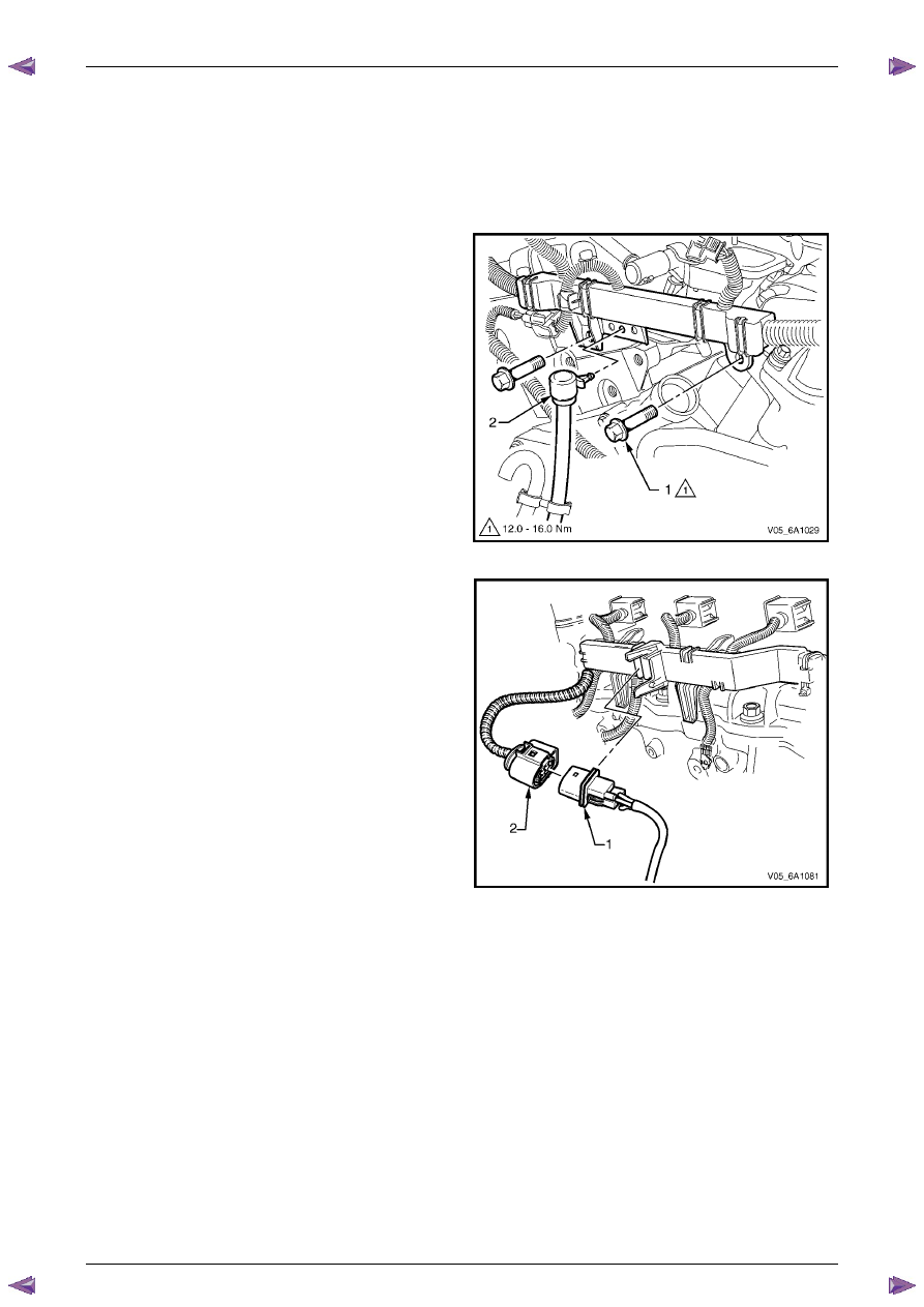
3
Remove the two bolts (1) attaching the engine wiring
harness former to the rear of the cylinder heads.
4
Unclip the transmission vent tube (2) from the engine
wiring harness.
Figure 6A1 – 61
5
Disconnect the oxygen sensor wiring harness
connector (1) from the engine wiring harness (2), left-
hand shown, right-hand similar.
Figure 6A1 – 62
Нет комментариевНе стесняйтесь поделиться с нами вашим ценным мнением.
Текст