Isuzu KB P190. Manual — part 718
Engine Mechanical – V6
Page 6A1–95
Page 6A1–95
6
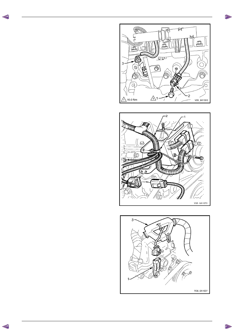
Remove the bolt (1) attaching the ground connector
(2) to the cylinder head.
7
Fro the left-hand side, disconnect the engine coolant
temperature (ECT) sensor wiring connector (3).
8
Unclip the engine wiring harness retaining lugs from
the side of the camshaft cover.
Figure 6A1 – 63
9
For the right-hand side, remove the engine wiring
harness retaining clip (1) from the engine control
module (ECM) bracket (2).
Figure 6A1 – 64
10
Disconnect the camshaft position (CMP) sensor wiring
connector (1).
11
Unclip the engine wiring harness retaining lug (3) from
the front of the camshaft cover.
12
Remove the ignition coil assemblies; refer to
Section 6C1-3 Engine Management – V6 – Service
Operations
.
13
Move the engine wiring harness clear of the camshaft
cover.
Figure 6A1 – 65
Engine Mechanical – V6
Page 6A1–96
Page 6A1–96
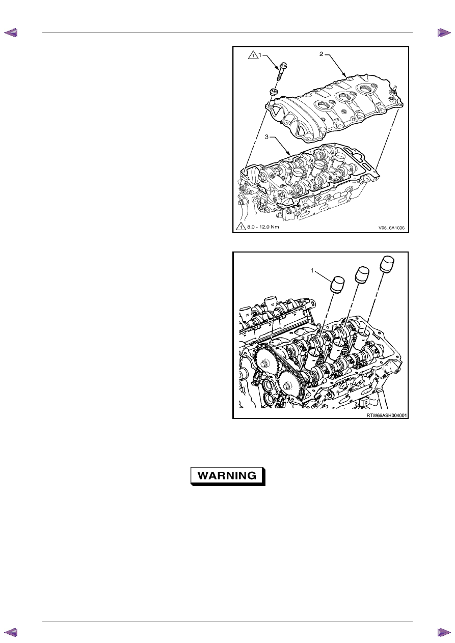
14
Remove the bolt (1), 13 places, attaching the camshaft
cover (2) to the cylinder head (3).
15
Remove the cover and discard the seal.
Figure 6A1 – 66
16
Install Tool No. EN-46101 (1) to the spark plug tubes
of the cylinder head to prevent entry of dirt into the
combustion chamber.
Figure 6A1 – 67
Clean and Inspect
Safety glasses must be worn when using
compressed air.
1
Clean the camshaft cover with suitable cleaning solvent and blow dry with compressed air.
2
Inspect the cover for cracking and distortion.
3
Check the spark plug tube seals for damage.
4
If the camshaft cover is damaged in any way that will affect it’s performance to seal and stop the ingress of dirt,
replace the camshaft cover.
Engine Mechanical – V6
Page 6A1–97
Page 6A1–97
Reinstall
Reinstallation of the camshaft cover assembly is the reverse of the removal procedure, noting the following:
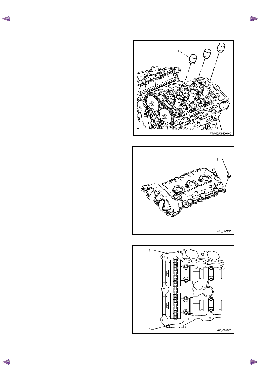
1
If not already fitted, install Tool No. EN-46101 (1) to
the spark plug tubes of the cylinder head.
Figure 6A1 – 68
2
Ensure that the grommet (1), 13 places, is correctly
seated in its hole.
3
Wipe the camshaft cover sealing surface on the
cylinder head with a clean lint free cloth.
Figure 6A1 – 69
4
Ensure that a new seal is correctly fitted to the
camshaft cover. Place a 3 mm bead of RTV sealant on
the join line of the engine front cover (1).
Figure 6A1 – 70
Engine Mechanical – V6
Page 6A1–98
Page 6A1–98
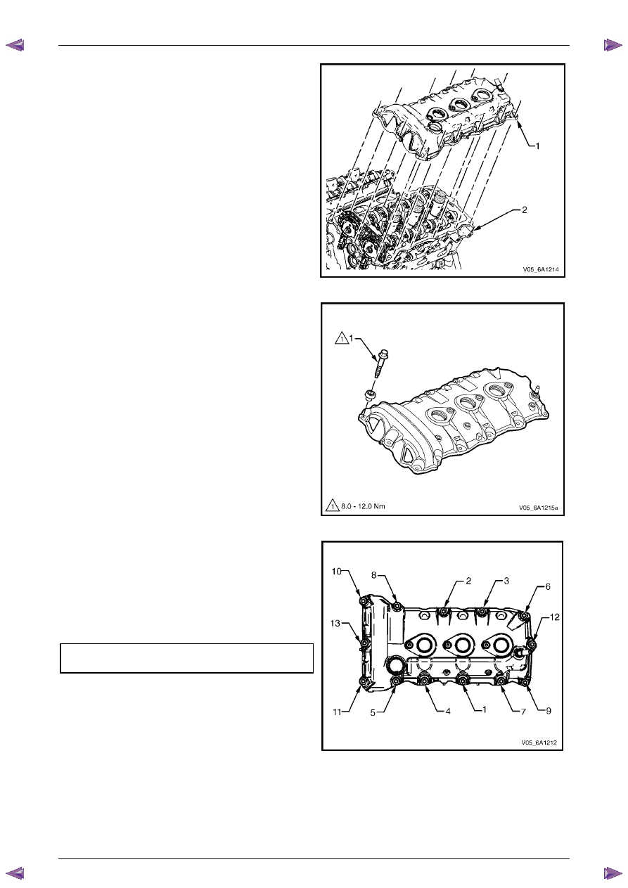
5
Place the camshaft cover (1) into position onto the
cylinder head (2).
Figure 6A1 – 71
6
Loosely install the camshaft cover bolt (1), 13 places.
Figure 6A1 – 72
7
Tighten the camshaft cover bolts to the correct torque
specification, in the sequence shown.
Camshaft cover attaching bolt
torque specification . . . . . . . . ...8.0 – 12.0 Nm
Figure 6A1 – 73
Нет комментариевНе стесняйтесь поделиться с нами вашим ценным мнением.
Текст