Isuzu KB P190. Manual — part 1015

7A2-94 TRANSMISSION CONTROL SYSTEM (AW30–40LE)
Condition For Setting The DTC
The TCM detects following conditions for 0.5 seconds
continuously at shifting.
• Voltage at connector pin is 0V when solenoid is “ON”.
(DTC P0973)
• Voltage at connector pin is ignition voltage when
solenoid is “OFF”. (DTC P0974)
Action Taken When The DTC Sets
• No L-up control.
• No line pressure reduction control at gear change.
• No torque reduction control.
• No squat control.
• No slope control.
• No line pressure reduction control at garage.
• No input revolution sensor failure detection.
• No shift solenoid failure detection.
• No L-up solenoid failure detection.
• Change to emergency mode.
• Check Trans “ON”.
• DTC stored.
• MIL request “ON”. (EURO 4 only)
Conditions For Clearing The DTC
• The DTC can be cleared from the TCM history by
using a scan tool.
• The DTC will be cleared from history when the
vehicle has achieved 40 warm-up cycles without a
failure reported.
• After more than 1 second has elapsed after the
ignition key has been turned “ON”, short between
No.11 and No.4 (ground) of DLC (Data Link
Connector). Then, after 1 second, but within 6
seconds, discontinue shorting.
Diagnostic Aids
• Inspect the wiring for poor electrical connection at the
TCM. Look for possible bent, backed out, deformed
or damaged terminals. Check for weak terminal
tension as well. Also check for a chafed wire that
could short to bare metal or other wiring.
Inspect for a broken wire inside the insulation.
• When diagnosing for a possible intermittent short or
open condition, move the wiring harness while
observing test equipment for a change.
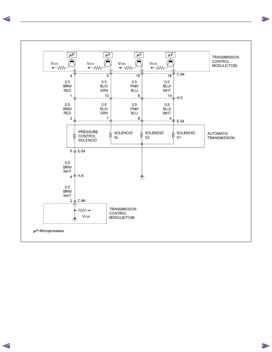
Circuit/System Testing DTC P0973 or P0974
Step Action Value(s)
YES
NO
1
Was the On-Board Diagnostic (OBD) System Check
performed?
— Go
to
Step 2
Go to OBD
System Check
2
1. Install a scan tool.
2. Start the engine.
3. Depress the brake pedal and place the select lever
in D position.
4. Press the 3rd start switch. (Turn the 3rd start
switch “ON”.)
5. Press the 3rd start switch again. (Turn the 3rd start
switch “OFF”.)
Does a scan tool indicate DTC P0973 or P0974?
— Go
to
Step 3
Refer to
Diagnostic Aids
3
1. Turn “ON” the ignition with the engine “ON”.
2. Place the selector lever in the “P” position.
3. Measure the voltage between terminal C94-16 and
terminal C94-1 (GND) on the TCM pigtail
connector by 5-8840-0285-0 DMM.
Is the voltage specified value?
8
∼
16V Go
to
Step 4
Go to Step 10

TRANSMISSION CONTROL SYSTEM (AW30–40LE) 7A2-95
Step Action Value(s)
YES
NO
4
1. Turn “OFF” the ignition.
2. Disconnect the TCM connector (C-94).
3. Turn “ON” the ignition.
4. Measure the voltage between terminal C94-16 and
terminal C94-1 by 5-8840-0285-0 DMM.
Is the voltage specified value?
0V Go
to
Step 5
Go to Step 7
5
1. Turn “OFF” the ignition.
2. Measure the resistance between terminal C94-16
and body ground by 5-8840-0285-0 DMM.
Is the resistance specified value?
11
∼15Ω Go
to
Step 9
Go to Step 6
6
1. Disconnect the automatic transmission connector
(E-54).
2. Measure the resistance between terminal E54-4
and body ground by 5-8840-0285-0 DMM.
Is the resistance specified value?
11
∼15Ω Go
to
Step 7
Go to Step 8
7
1. Check for open or short in the wire between
terminal C94-16 and terminal E54-4.
2. Repair or replace the wire between terminal C94-
16 and terminal E54-4.
Is the action complete?
— Go
to
Step 11 —
8
Replace the S1 solenoid.
Is the action complete?
— Go
to
Step 11 —
9
1. Clear the DTC.
2. Perform the test-driving.
3. Check the DTC.
Was DTC P0973 or P0974 stored?
— Go
to
Step 10
Refer to
Diagnostic Aids
10
Replace the TCM.
Important: The replacement TCM must be
programmed (Refer to SPS for procedure).
Is the action complete?
— Go
to
Step 11 —
11
1. Reconnect all previously disconnected harness
connector(s).
2. Clear the DTCs with a scan tool.
3. Turn “OFF” the ignition.
4. Start the engine.
5. Operate the vehicle within the Conditions For
Running the DTC. You may also operate the
vehicle within the conditions that you observed
from the Freeze Frame/ Failure Records.
Did the DTC fail this ignition?
—
Go to Step 2 Go
to
Step 12

7A2-96 TRANSMISSION CONTROL SYSTEM (AW30–40LE)
Step Action Value(s)
YES
NO
12
Observe the stored information, Capture info with a
scan tool.
Are there any DTCs that you have not diagnosed?
—
Go to
Diagnostic
Trouble Code
(DTC) List
Verify repair
TRANSMISSION CONTROL SYSTEM (AW30–40LE) 7A2-97
DTC P0976 or P0977 (Flash Code 32)
RTW77ALF001501
Circuit Description
The shift solenoid S2 changes the hydraulic route with
the signals from the TCM according to the vehicle
speed and the throttle opening to control shifting. When
the shift solenoid S1 or S2 fails, the hydraulic circuit is
mechanically operated as a backup.
Condition For Running The DTC
All of the following conditions are met.
(1) All of the following conditions are met for 2
seconds or more continuously.
• The supply voltage is more than 10.2 volts and
less than 15.5 volts.
(2) Not emergency mode.
(3) 0.025 seconds or more passed after the state of
power “ON” solenoid is changed.
(4) All of the following conditions are met.
• Device Control is not operating.
• Disable Normal Communication is receiving
enable.
• DTC Clear is not operating.
Нет комментариевНе стесняйтесь поделиться с нами вашим ценным мнением.
Текст