Isuzu KB P190. Manual — part 674
Engine Mechanical – V6
Page 6A1–217
Reassemble
Piston and Piston Pin
CAUTION
The arrow located on top of the piston must
point toward the front of the engine.
N O T E
The connecting rod is non-directional and may
be assembled/reassembled to the piston in
either direction.
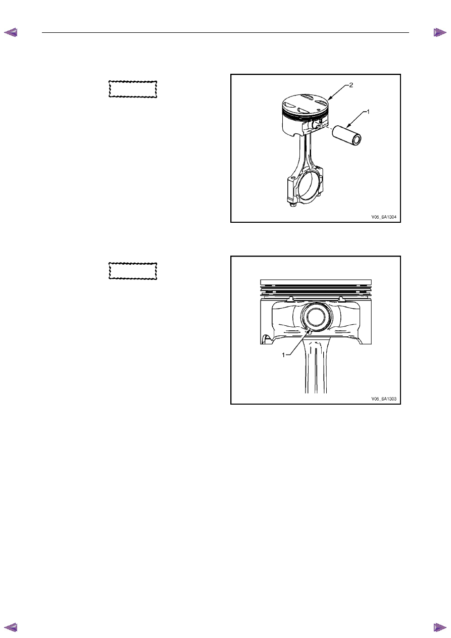
1
Lubricate the piston pin (1) bores in the piston (2) and
the connecting rod with clean engine oil.
2
Assemble the piston and piston pin to the connecting
rod. Correctly orient the piston when reusing a
marked connecting rod.
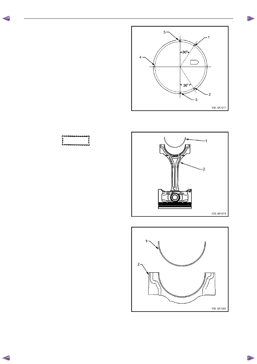
3
Align the piston pin bore with the connecting rod pin
bore.
4
Slide the piston pin into the piston and the connecting
rod.
Figure 6A1 – 395
CAUTION
New piston pin retainers must be used.
Never reuse the piston pin retainers.
5
Install new piston pin retainers (1).
6
Ensure the piston pin retainers are fully seated in their
grooves.
7
Repeat steps 1 to 6 for the remaining pistons.
Figure 6A1 – 396

Engine Mechanical – V6
Page 6A1–218
Piston Ring
N O T E
The ends of the expander must be facing
toward the top of the piston.
1
Correctly orient the oil control ring expander (1)
before installation.
Figure 6A1 – 397
2
Using a piston ring expander, install the oil control
ring assembly using the following procedure:
3
Install the expander ring (3).
4
Install the two oil scraper rings (4). Expand the rings
only enough to clear the piston diameter. Over-
expanding the piston rings will distort or crack the
rings.
5
Install the second (2) and top (1) piston rings as
follows.
Figure 6A1 – 398
6
Using the ring expander (1), install the second piston
ring (2) onto the piston (3). Do not over-expand the
ring. Repeat for the top ring.
Figure 6A1 – 399
Engine Mechanical – V6
Page 6A1–219
7
Once the rings are installed, set the ring gaps for the
oil control, second and top ring as follows. Use the
piston location arrow for reference.
•
Lower oil control ring position (1).
•
Upper oil control ring position (2).
•
Top ring position (3).
•
Oil control ring expander position (4).
•
Second ring position (5).
Figure 6A1 – 400
Connecting Rod Bearing
CAUTION
If the connecting rod bearings have been
used in a running engine, they must be
replaced with new connecting rod bearings
for reassembly.
1
Clean the connecting rod (2) and the connecting rod
cap bearing bore with a lint-free cloth.
2
Clean the oil from behind the connecting rod bearing
halves.
3
Install a new upper connecting rod bearing (1) into
position. Roll the bearing into position so the lock tang
engages the alignment slot. The bearing must fit flush
in the connecting rod.
Figure 6A1 – 401
4
Install the lower connecting rod bearing (1) into
position in the connecting rod cap (2).
5
Roll the bearing into position so the lock tang
engages the alignment slot. The bearing must fit flush
with the connecting rod cap.
Figure 6A1 – 402

Engine Mechanical – V6
Page 6A1–220
Reinstall
Piston Connecting Rod and Connecting Rod Bearing Installation
CAUTION
The piston is directional and must be
installed in the engine block in the correct
direction. The locating arrow on the top of
each piston must be pointing toward the
front of the engine.
1
Liberally lubricate the cylinder walls, piston rings and
piston skirts with engine oil.
2
Select the correctly numbered piston/connecting rod
assembly for the cylinder. A dot (1) showing correct
piston orientation is located on the top of the piston.
Figure 6A1 – 403
3
Install connecting rod guide pin set, Tool No.
EN-46121 (1) into the connecting rod bolt holes.
Figure 6A1 – 404
4
Compress the piston rings using a commercially
available ring compressor.
CAUTION
Extreme care must be used when installing
the piston and connecting rod to ensure the
rod does not scrape or nick the cylinder
bore, oil jets, or crankshaft surfaces.
5
Using both hands from the top and bottom of the
cylinder, slowly guide the piston (2) and connecting
rod assembly into the cylinder. Do not allow the
connecting rod to contact the cylinder wall.
6
When the ring compressor contacts the deck surface,
gently tap the piston into the cylinder using the handle
end of a dead-blow hammer. Guide the connecting
rod onto the crankshaft bearing journal using
connecting rod guide pin set, Tool No. EN-46121 (1)
while gently tapping the piston into the cylinder with a
soft-blow hammer.
Figure 6A1 – 405
Нет комментариевНе стесняйтесь поделиться с нами вашим ценным мнением.
Текст