Isuzu KB P190. Manual — part 542

6D3-20 STARTING AND CHARGING SYSTEM
Load regulation test
Increase the engine speed until the generator is running at
6000 rpm, increase the load to 90% of full output a decrease in
the regulating voltage should not exceed 0.50 volts for 12 v
and 0.70 v for 24 v regulators of the readings obtained in the
previous test. If so, the regulator is defective.
Generator output test at full load
Increase engine speed until the altenator is running at 6000
rpm, switch on electrical loads until the generator voltage
drops to 13.5 volts for 12 v systems and 26 volts for 24 v
systems, full outut should be obtained under these conditions.
It may be necessary to adjust engine speed to maintain
altenator speed. If sufficient electrical loads are not available a
carbon pile resistance can be connected across the battery
and adjusted until maximum output is obtained.
Keep the time for this test to a minimum to avoid undue
heating and high engine speeds.
STARTING AND CHARGING SYSTEM 6D3-21
Technical Data
(mm)
Brush wear - Minimum Length
3.8
Sliprings -
Minimum
Diameter
26.7
Sliprings -
Trueness
<0.06
Pole claws - Trueness
<0.05(93.25
±0.05)
Torque
N.m(kgf
⋅m)
Pulley retaining nut
54-68(5.5-6.9)
Capacitor retaining screw
2.7-3.8(0.3-0.4)
Capacitor whiz nut
1.5-2.2(0.1-0.2)
B+ terminal nut M8
7.5-8.5(0.8-0.9)
B+ terminal rectifier nut
6.0-7.5(0.6-0.8)
Regulator retaining screw
1.6-2.3(0.1-0.2)
Rectifier retaining screw
1.6-2.3(0.1-0.2)
Bearing retaining plate screw 2.1-3.0(0.2-0.3)
Through bolt
3.8-5.5(0.4-0.6)
Winding resistance(between phases)
(
Ω)
Stator
Rotor
70 Amp generator
0.086+10%
2.6
±0.13
85 Amp generator
0.058+10%
2.6
±0.13
90 Amp generator
0.056+10%
2.6
±0.13
Warning lamp fault indication
Fault running
Generator not
running Ignition ON
Generator
Iginiton ON
Generator out cable
O/C
ON
ON
Battery "S" cable O/C
ON
ON
Battery overcharged
ON
ON
Positive diode short
OFF
ON
Negative diode short
ON
ON
Positive diode open
ON
OFF
Negative diode open
ON
OFF
Phase voltage sensing
ON
ON
cable open circuit
Power transistor
shorted
ON
ON
Warnign lamp driver
O/C
OFF
OFF
6D3-22 STARTING AND CHARGING SYSTEM
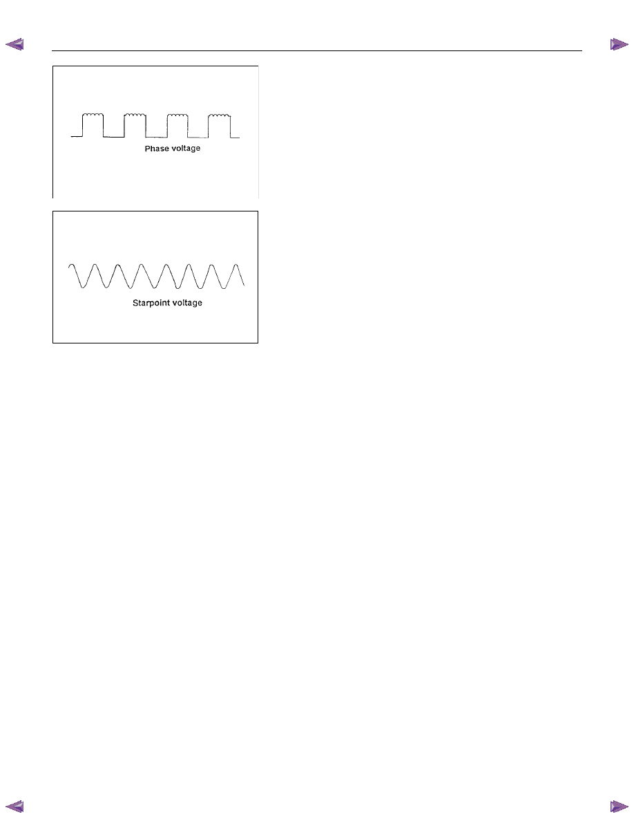
Output wave forms for phase and startpoint connections.
Note; the average of these two waveforms are identical from
no load to 100% output of rated load.
Voltage phase = Voltage startpoint
6.9v@ rated output 7.2v@ Zero output
Note: The phase frequency is one third of the startpoint
frequency.
SECTION 6E
TABLE OF CONTENTS
C24SE ENGINE DRIVEABILITY AND EMISSIONS
ABBREVIATIONS CHARTS . . . . . . .
ECM Circuit Diagram (1/2) . . . . . . .
ECM Circuit Diagram (2/2) . . . . . . .
GROUND POINT CHART - LHD G.EXP (1/4)
GROUND POINT CHART - RHD G.EXP (1/4)
LOCATION . . . . . . . . . . . . ...
LOCATION . . . . . . . . . . . ..
LOCATION - LHD . . . . . . . . ...
LOCATION - RHD . . . . . . . . ...
CONNECTOR LIST . . . . . . . . . ..
RELAY AND FUSE . . . . . . . . . ...
(LHD & RHD) . . . . . . . . . . ...
FUSE AND RELAY LOCATION (LHD & RHD)
ECM WIRING DIAGRAM (1/9) . . . . . .
ECM WIRING DIAGRAM (2/9) . . . . . .
ECM WIRING DIAGRAM (3/9) . . . . . .
ECM WIRING DIAGRAM (4/9) . . . . . .
ECM WIRING DIAGRAM (5/9) . . . . . .
ECM WIRING DIAGRAM (6/9) . . . . . .
ECM WIRING DIAGRAM (7/9) . . . . . .
ECM WIRING DIAGRAM (8/9) . . . . . .
ECM WIRING DIAGRAM (9/9) . . . . . .
ECM CONNECTOR PIN ASSIGNMENT &
OUTPUT SIGNAL . . . . . . . . .
GENERAL DESCRIPTION FOR ECM AND
SENSORS . . . . . . . . . . . ...
Engine Control Module (ECM) . . . . ...
Manifold Absolute Pressure (MAP) Sensor
Throttle Position Sensor (TPS) . . . . ..
Idle Air Control (IAC) Valve . . . . . ...
Crankshaft Position (CKP) Sensor . . .
Knock Sensor (KS) . . . . . . . . .
Engine Coolant Temperature (ECT) Sensor
Intake Air Temperature (IAT) Sensor . .
Vehicle Speed Sensor (VSS) . . . . .
METERING . . . . . . . . . . . ..
Battery Voltage Correction Mode . . . ...
Clear Flood Mode . . . . . . . . . ..
Deceleration Fuel Cutoff (DFCO) Mode .
Engine Speed/ Vehicle Speed/ Fuel Disable
Mode . . . . . . . . . . . . . .
Acceleration Mode . . . . . . . . . .
Fuel Cutoff Mode . . . . . . . . . ...
Starting Mode . . . . . . . . . . .
Run Mode . . . . . . . . . . . . ..
Fuel Metering System Components . . ..
Fuel Injector . . . . . . . . . . . ...
Fuel Pressure Regulator . . . . . . .
Fuel Rail . . . . . . . . . . . . . .
Fuel Pump Electrical Circuit . . . . . ...
Thottle Body Unit . . . . . . . . . ...
GENERAL DESCRIPTION FOR ELECTRIC
IGNITION SYSTEM . . . . . . . . .
Spark Plug . . . . . . . . . . . . .
GENERAL DESCRIPTION FOR EVAPORATIVE
EMISSION SYSTEM . . . . . . . ...
EVAP Emission Control System Purpose ..
EVAP Emission Control System Operation
System Fault Detection . . . . . . . ..
POSITIVE CRANKCASE VENTILATION (PCV)
SYSTEM . . . . . . . . . . . . ..
Crankcase Ventilation System Purpose .
A/C CLUTCH DIAGNOSIS . . . . . .
A/C Clutch Circuit Operation . . . . . ..
A/C Clutch Circuit Purpose . . . . . .
A/C Request Signal . . . . . . . . ...
ISUZU STRATEGY BASED DIAGNOSTICS
Overview . . . . . . . . . . . . .
STRATEGY BASED DIAGNOSTICS CHART
Diagnostic Thought Process . . . . . ..
1. Verify the Complaint . . . . . . . ..
2. Perform Preliminary Checks . . . . ..
3. Check Bulletins and Troubleshooting Hints
4. Perform Service Manual Diagnostic Checks 6E-63
5a and 5b. Perform Service Manual Diagnostic
Procedures . . . . . . . . . . . ..
5c. Technician Self Diagnoses . . . . ..
5d. Intermittent Diagnosis . . . . . . ..
6E–1
ENGINE DRIVEABILITY AND EMISSIONS
Нет комментариевНе стесняйтесь поделиться с нами вашим ценным мнением.
Текст