Isuzu KB P190. Manual — part 541
6D3-16 STARTING AND CHARGING SYSTEM
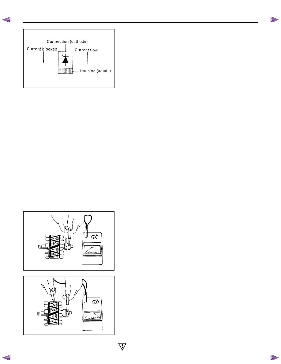
Readings for Zener diode groups 011 to 042
Zener voltage at
5Ma.
Positive
diode
Negative
diode
Fordward
current Rating
17.8v-19.2v
011
012
25A
18.8v-20.2v
013
014
25A
19.8v-21.2v
015
016
25A
20.8v-22.2v
017
018
25A
21.8v-23.2v
019
020
25A
22.8v-24.2v
021
022
25A
17.8v-19.2v
031
032
35A
18.8v-20.2v
033
034
35A
19.8v-21.2v
035
036
35A
20.8v-22.2v
037
038
35A
21.8v-23.2v
039
040
35A
22.8v-24.2v
041
042
35A
Note: Diode number is stamped on the rear of the diode.
2. Stator
Inspect the stator insulation resistance to ground with an
insuation tester or a series test lamp up to 110 volts.
The insulation resistance must be greater than 1 megohm.
The winding reisistance is measured between phases using a
low reading ohmmeter designed for this purpose, the values
are given at the rear of this instruction.
3. Rotor
Inspect the rotor for insulation resistance to ground using an
insulation tester or a series test lamp up to 110 volts.
The insulation resistance must be grater than 1 megohm.
Measure the rotor resistance between the sliprings using an
ohmmeter or apply 12 volts across the sliprings and measure
the rotor current flow, then divide 12 by the measured current,
the results is the rotor resistance in ohms. values are given at
the rear of this instruction.
If the sliprings are worn or out of round they must be re-
machined to a minimum diameter or 26.7 mm and should have
a runout not exceeding 0.060mm. If the slipring is below these
limits it must be replaced with a new one.
Warning; extreme care must be exercised when machining
the slipring as it is possible for the turning tool to foul the
STARTING AND CHARGING SYSTEM 6D3-17
fan.
4. Replacing the brushes (inbuilt regulator)
Check the brushes for length, this is measured from the brush
holder to the end of the brush along it's centre line. Also
inspect for any sideways wear. If worn replace both brushes.
The minimum length is 3.8mm. Inspect the brush springs for
signs of corrosion or loss of tension or uneven tension.
Replacing the brushes, using a soldering iron apply heat to the
soldered joints on the rear of the brush holder of the regulator,
using a small lever prise up the retaining tabs to release the
brush lead and spring. Thread the new brush lead up the
brush holder along with the spring, pull the lead through the
tabs until the brush is protruding 12mm from the holder.
Bend down the tabs and solder the brush lead taking care not
to allow the solder to run up the lead which will reduce
flexibility. Use 60/40 resin cored solder.
5. Ball bearing
Please note the bearings used in this KCA generator are a
high
tolerance type, only fully sealed bearings of the same
specification are to be used as replacements. It is
recommended that the bearings be replaced during the
reconditioning process to restore the unit to original
specification.
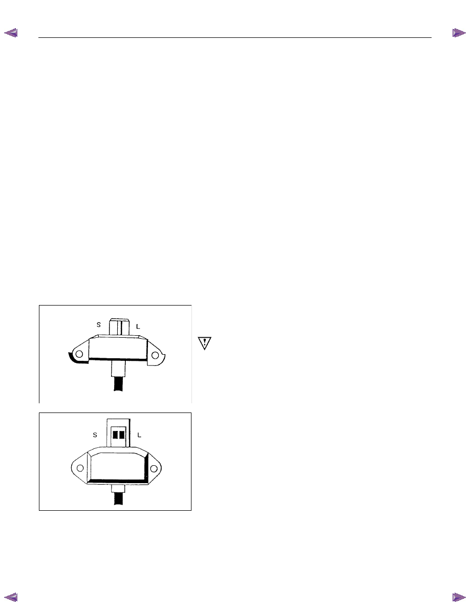
6. Regulator
The regulator can only be tested when fitted into an altenator.
Warning: do not reverse"S" and "L" connections or put 12
volt supply to "L" terminal, this connection must not be
used as a supply source other than to supply the
requirements of the warning lamp 2(watts).
Such action will destroy the regulator warning lamp
circuit.
For test voltages refer to Generator output testing section.
See also additional information on regulator function earlier in
this instruction.

6D3-18 STARTING AND CHARGING SYSTEM
Reassembly
Generator
(a) Press new bearing onto slipring end of the rotor taking care
to aplly the force to the bearing inner race only, otherwise
the bearing will be noisy and it's life will be shortened.
(b) Fit a new bearing to the drive end housing, fit the bearing
plate, and four retaining screws, press the rotor into the
bearing, using a support tool to take the thrust against the
bearing inner.
The support is fitted from the pulley side of the bearing. In
this way the thrust is not taken by the drive end housing.
(c) To fit pulley, mount an 8mm Allen key in the vice with the
short end upwards, place a 24mm ring spanner on the shaft
nut, position the internal hexagon of the rotor shaft onto the
Allen key, tighten the nut to the required torque(See torque
chart)
(d) Inspect the bearing support ring for signs of damage, if in
doubt replace the ring by pressing it into the housing by
hand, do not use excessive force.
(e) To refit the rectifier, fit new mica washers to the positive
heatsink B+ bolt and retaining screw each washer must
have heatsink compound applied to both surfaces before
fitting.
Fit the three retaining screws to the rectifier then install into
slipring end housing. Tighten the B+ bolt to the reuired
torque.
(f) To refit the stator, make sure the spigot surface are clean
and free from damage, fit the stator into the slipring end
housing noting the correct lead connection positioning. Fit
the stator leads into the wire loops in the recrifier. Using a
pair of pliers squeeze the loop to retain the stator lead prior
to soldering. Repeat for each lead in turn, solder the leads
into position using 60/40 resin cored solder. Make sure the
leads will be clear of the internal fan when the rotor is
assmebled into the stator.
(g) Carefully install the rotor into the stator/slipring end housing
assembly, noting the alignment of the housings and through
bolt holes. Fit the through bolts making sure the stator is
seated correctly, tighten the through bolts to the correct
torque setting (uneven torque can produce magnetic noise
levels above normal).
(h) Fitting the regulator. Compress the brushes into the brush
holder by hand, slip the regulator through the opening in the
rear of the slipring end housing until the brushes come in
contact with the slipring. Press the regulator towards the
slipring until the holes are aligned then fit the retaining
screws and tighten.

STARTING AND CHARGING SYSTEM 6D3-19
Inspection
Generator
Before any in field testing can be undertaken it is important
that the battery's conditions is established and the terminals
are clean and tight.
Check the condition of the generator drive belt and ensure that
it is adjusted in accordance with the engine manufacturer's
recommnedations.
Battery conditions:
Note: This assessment may be difficult with maintenance free
assemblies.
Test the specific gravity of the individual cells the readings
should be within 10 points of each other, it is recommended
that the average SG should be 1.260 or higher.
A load test should be carried out to determine the ability of the
battery to supply and accept current. This is a good indicator
as to the general condition of the battery.
A load equal to the normal starting current should be placed
across the battery, the duration of this load test should not
exceed 10 seconds, during this time the terminal voltage
across the battery should not drop below 9.6 volts. Observe
each cell for signs of excessive gas liberation, usuall an
indication of cell failure.
If the battery test is clear proceed with the Generator tests as
follows.
Care should be taken when making the following connections.
It is recommended that the battery negative terminal be
disconnected before the test meters are connected, and
reconnecting the negative terminal when the meters are
inserted into the circuit under test. The warning lamp in the D+
circuit should not exceed 2 watts.
Regulating voltage test on the vehicle.
Connect a voltmeter to the generator, the positive lead to the
B+ terminal and the nagative lead to the generator casing.
Select the voltage range to suit the system, i.e. 20v for 12 volt
sysytems or 40v for 24 volt systems. Connect an ammeter in
series with the main output cable from the B+ terminal on the
generator, the range selected must be capable of reading the
maximum output from the generator.
Note the voltmeter reading before starting the engine. This
reading should increase when the engine is running indicating
generator output, start the engine and increase the engine
speed until the generator is running at 4000 rpm, switch on
vehicle loads of 5-10 A is indcated on the ammeter, the
voltmeter shoud read 14.0-14.2 v for a 12 volt system, for a 24
volt system the readings should be 5-10 A and 27.7-28.5 volts.
Нет комментариевНе стесняйтесь поделиться с нами вашим ценным мнением.
Текст