Isuzu KB P190. Manual — part 685
Engine Mechanical – V6
Page 6A1–261
N O T E
All swarf must be removed from the tapped hole
prior to insert installation.
Safety glasses must be worn when using
compressed air.
13
Using compressed air, clean out any swarf.
Figure 6A1 – 508
N O T E
Do not allow oil or other foreign material to
contact the outside diameter (OD) of the insert.
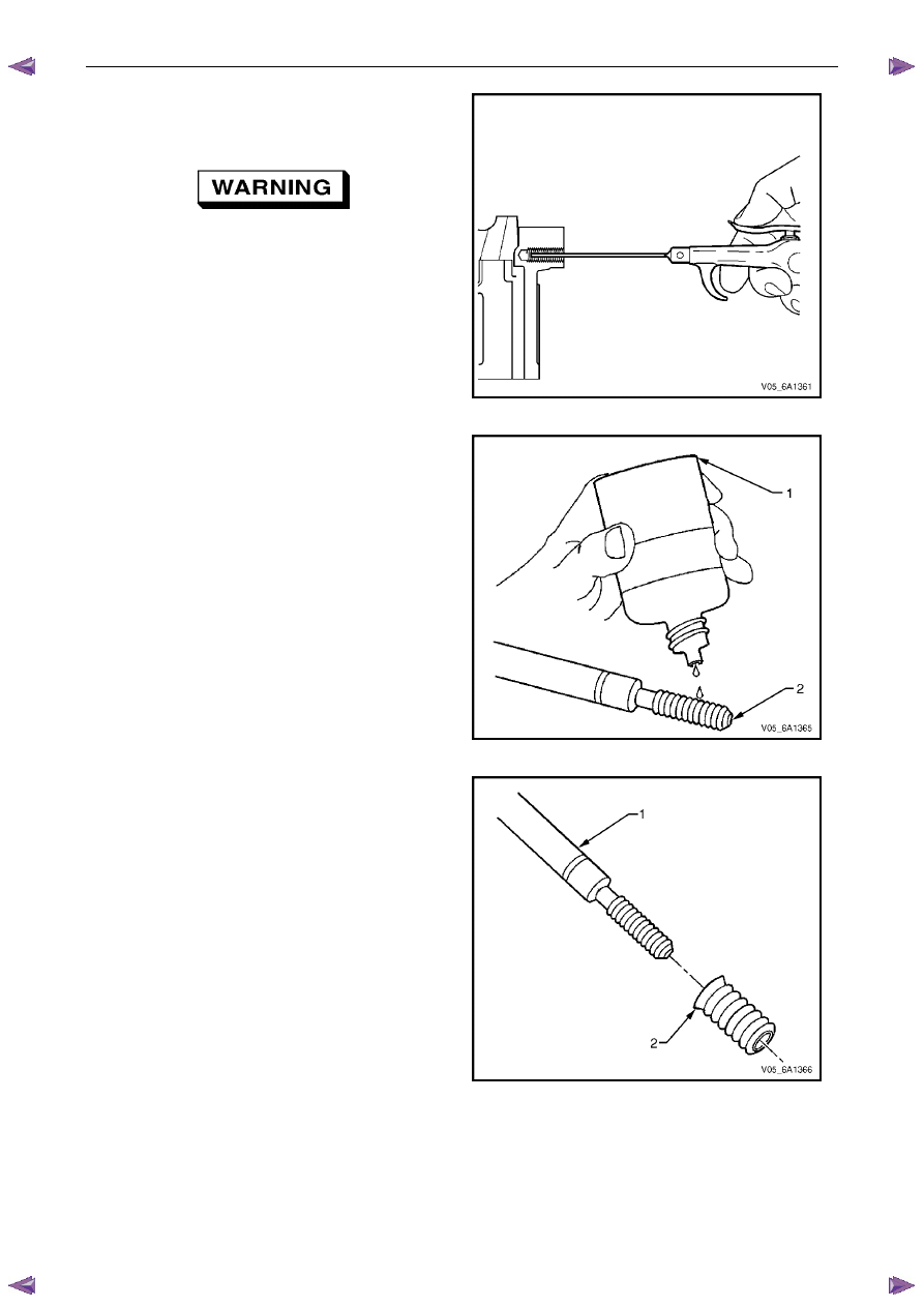
14
Lubricate the threads of the driver installation tool (2)
with the driver oil (1).
Figure 6A1 – 509
15
Install the insert (2) onto the driver installation tool (1).
Figure 6A1 – 510
Engine Mechanical – V6
Page 6A1–262
16
Apply thread lock sealant (1) such as Loctite 277® or
equivalent to the insert OD threads (2).
Figure 6A1 – 511
17
Install the insert and installation driver (1) into the
tapped hole by hand only.
18
Start the insert into the threaded hole.
CAUTION
If the insert will not thread down until the
flange contacts the counter-bored surface,
remove the insert immediately with a screw
extracting tool and inspect the tapped hole
for any remaining swarf and/or incorrect
tapping.
19
Install the insert until the flange of the insert contacts
the counter-bored surface.
N O T E
The driver installation tool will tighten up before
cutting completely through the insert. This is
acceptable. The threads at the bottom of the
insert are being formed and the insert is
mechanically locking the insert into the base
material threads.
20
Continue to rotate the driver installation tool through
the insert.
Figure 6A1 – 512
21
In order to completely form the new threads in the
insert, rotate the driver installation tool through the
insert until the mark on the driver installation tool (1)
aligns with the surface of the engine block deck (2).
22
Inspect the insert for correct installation into the
tapped hole.
Figure 6A1 – 513
Engine Mechanical – V6
Page 6A1–263
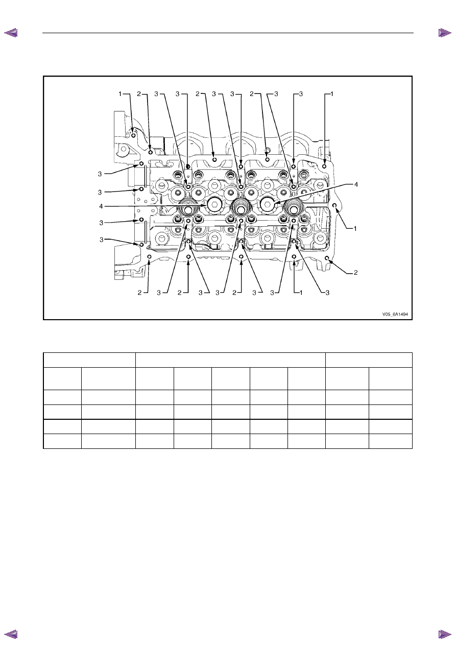
4.9
Thread Repair Specifications
Left-hand Cylinder Head Camshaft Cover Face
Figure 6A1 – 514
Legend
Hole
Tool Number J 42385
Max. Depth in mm
Number Thread
Size Drill
Counter-
bore
Tap Driver
Insert Drill
Tap
1
M6 x 1.0
201
202
203
204
205
22.5
18.0
2
M6 x 1.0
201
202
203
204
205
Thru
Thru
3
M6 x 1.0
701
n/a
203
204
205
28.5
24.0
4
M20 x 1.5
715
716
717
718
719
25.0
17.0
Engine Mechanical – V6
Page 6A1–264
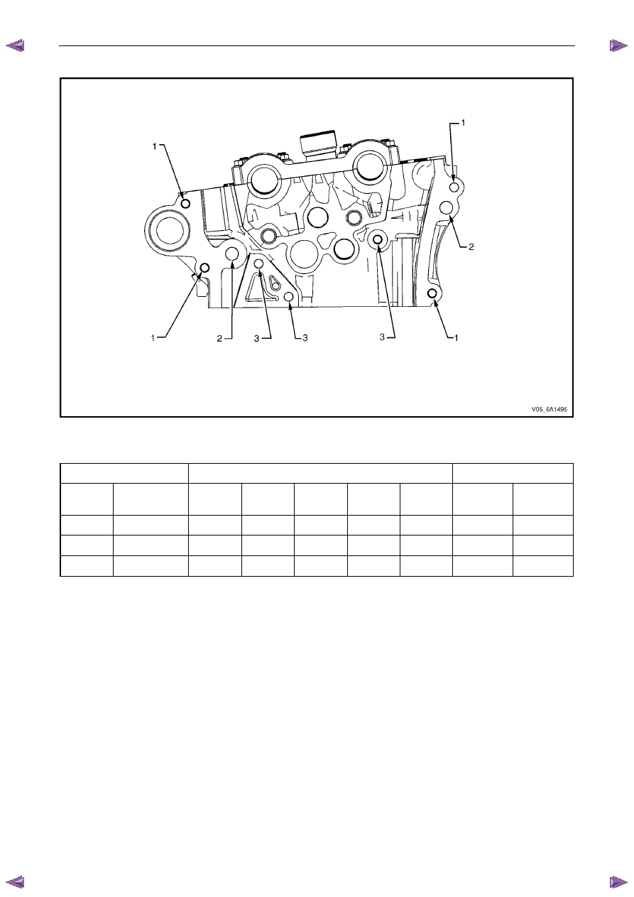
Left-hand Cylinder Head Front Face
Figure 6A1 – 515
Legend
Hole
Tool Number J 42385
Max. Depth in mm
Number Thread
Size Drill
Counter-
bore
Tap Driver
Insert Drill
Tap
1
M8 x 1.25
206
207
208
209
210
Thru
Thru
2
M12 x 1.75
856
857
858
859
416
40.0
32.5
3
M8 x 1.25
206
207
208
209
210
22.5
18.0
Нет комментариевНе стесняйтесь поделиться с нами вашим ценным мнением.
Текст