Isuzu KB P190. Manual — part 121
4B-40 REAR AXLE
Inspection and Repair
Make all necessary adjustments, repairs, and part
replacements if wear, damage, rust or other problems
are discovered during inspection.
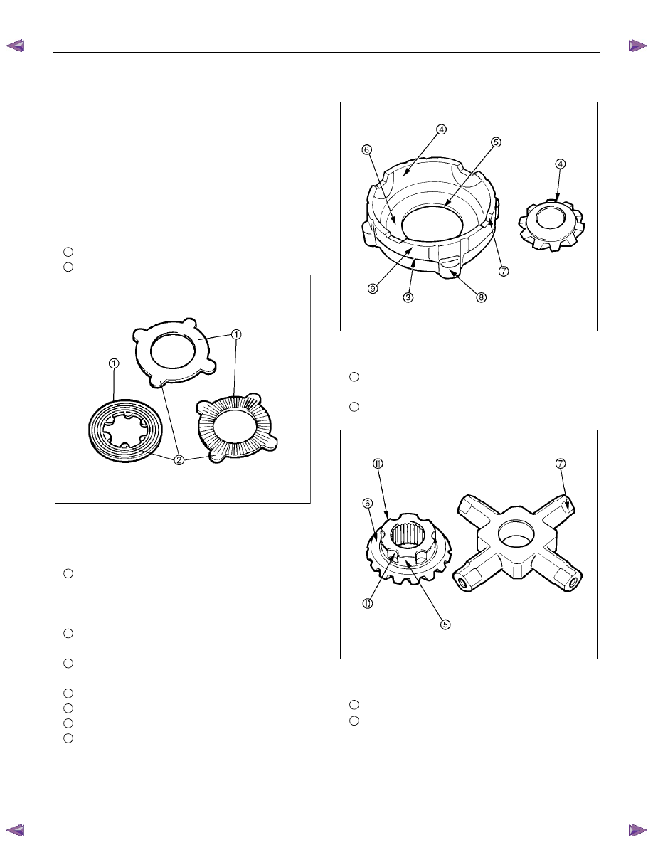
Visual Check
Inspect the following parts for wear, damage or other
abnormal conditions.
• Friction disc
• Friction plate
• Spring plate
1
Sliding surface
2
Protrusion
425RS056
Pressure ring
Check the parts for damage or other abnormal
conditions.
3
Sliding surface for friction disc
If dents or damages are discovered, grind them
with oil stone, and repair them with compound on
surface plate.
4
Sliding surface of pressure ring inner surface and
pinion gear.
5
Sliding surface of pressure ring bore and side
gear.
6
sliding surface of pressure ring and side gear.
7
Sliding surface of pressure ring and pinion shaft.
8
Mating surface to differential cage A.
9
Burrs or dents on sliding surface of pressure ring
and rear differential cage should be repaired,
using oil stone.
425RY00022
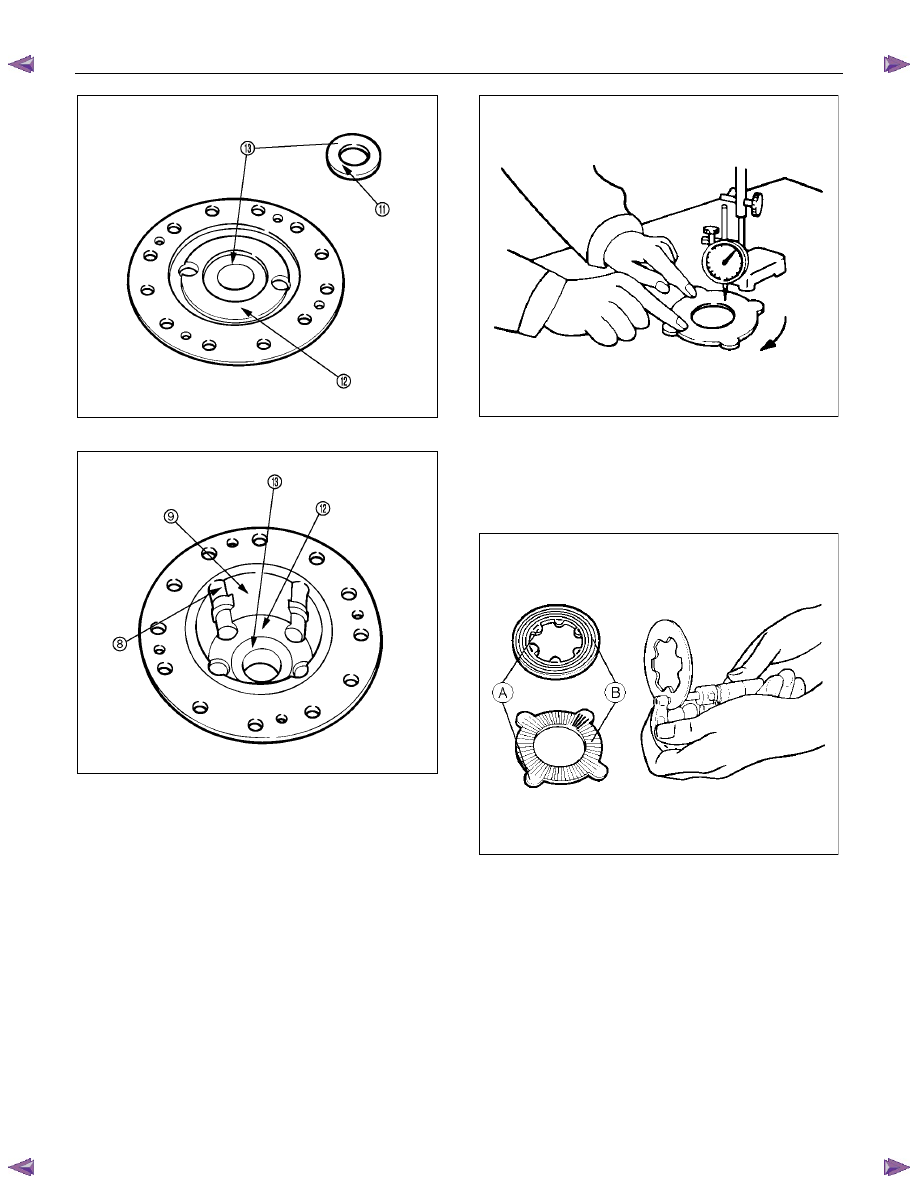
• Thrust Washer
10
Groove on side gear circumference small burrs of
dens should be repaired, using oil stone.
11
Sliding surface between side gear and thrust
washer.
425RY00024
• Differential cage A and B
12
Contact surface to spring plate
13
Differential cage A and B contact surfaces to
thrust washers Small burrs or dents should be
repair, using oil stone.
REAR AXLE 4B-41
425RY00025
425RY00023
Friction Disc and Friction Plate
• Check friction disc and friction plate for distortion.
Limit : 0.08 mm
425RS061
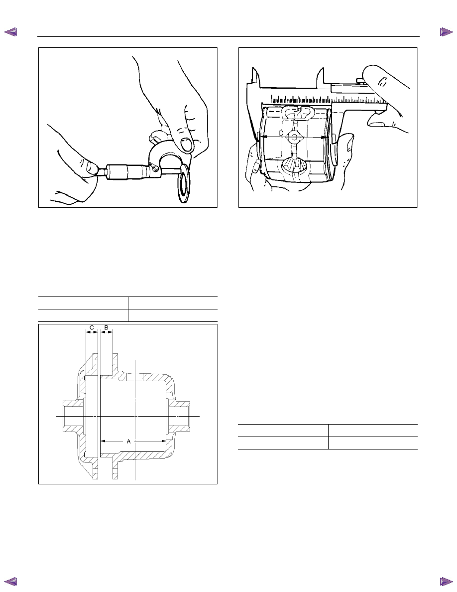
• Check friction plate and friction disc for wear.
Limit : (A-B)
0.1 mm
A : Protrusion Portion
B : Sliding Portion
425RS062
• Check thrust washer for wear.
Limit : 1.3 mm
4B-42 REAR AXLE
425RS063
Reassembly
Adjustment of Clearance between
Friction Disc and Plate
1. Measuring depth of differential case
mm(in)
Standard (A-B)
80.58 (3.17)
(C) 10.58
(0.42)
425RS064
2. Measuring overall length of pressure ring, friction
disc and plate assembly
• Assemble pinion shaft with pressure ring, then
friction disc and plate.
• Measure length between plates at both ends
over V-shape groove. (D)
425RS065
3. After A, B, C and D dimensions are measured,
perform adjustment with the following procedure.
• Measure spring plate :
1.75 mm (0.069 in)
× 4 pcs (E)
• Measure thickness of plate spring
Standard dimension :
1.75 mm (0.069 in)
× 2 pcs (F)
4. Select a friction disc or plate so that ((A-B+C) -
(D+E) = 0.06 to 0.20 mm (0.002 to 0.008 in.) and
also the difference in total dimension of friction
disc and plate and spring plate (left/right side)
does not exceed 0.05 mm (0.002 in.).
Thickness : 1.65, 1.75, 1.85 mm (0.065, 0.069,
0.073 in)
Adjusting Backlash of Side Gear in
Axial Direction
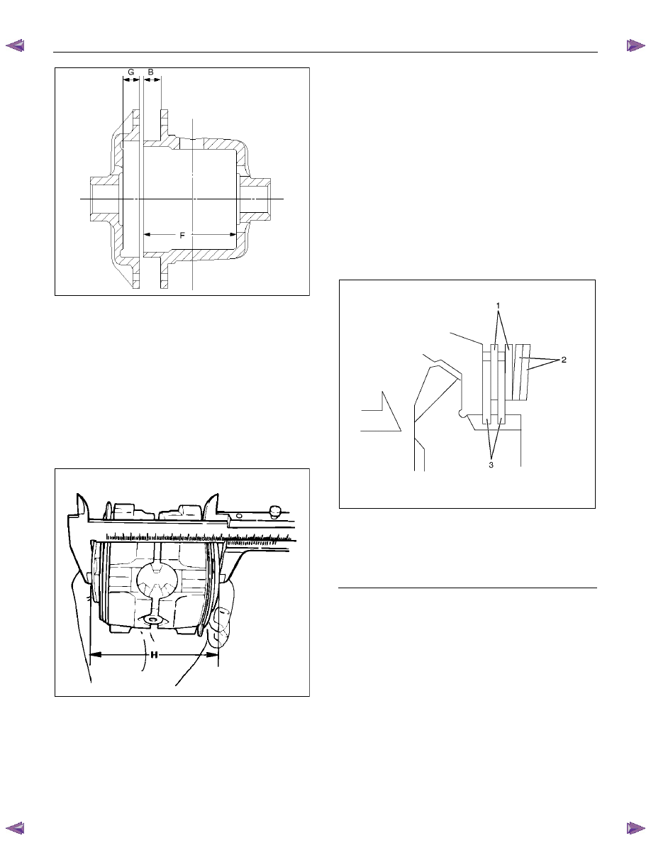
1. Measuring depth of differential case
mm(in)
Standard (F-B)
82.03 (3.23)
(G) 12.03
(0.47)
REAR AXLE 4B-43
425RS066
2. Measuring dimension between thrust washers at
both ends.
Assemble side gear, pinion, pinion shaft pressure
ring and thrust washer.
• Eliminate clearance by pushing pressure ring
against the pinion shaft in axial direction.
• Eliminate backlash by connecting side gear to
the pinion.
• Measure dimension between thrust washers
at both ends. (H)
425RS067
3. After each dimension is measured, perform
adjustment with the following procedure.
Adjust so that ((F-B) + G-H) = 0.05 to 0.2 mm
(0.002 to 0.008 in). Also, select a proper thrust
washer so that the dimension difference from
back face of the pressure ring to thrust washer
(left/right side) does not exceed 0.05 mm (0.002
in).
Thickness : 1.5, 1.6, 1.7 mm (0.059, 0.063, 0.067
in)
Note :
When reassembling, sufficiently apply gear oil on
every part, especially on sliding surface.
1. Install thrust washer in differential cage A and
B.
2. Assemble spring plate, friction plate and
friction disc as following illustration.
• Install spring plate with dished side turned
to the differential cage side.
425R300009
Legend
1.
Friction
Plate
2.
Spring
Plate
3.
Friction
Disc
4. Install pressure ring and side gear.
• Fit two side gears in two pressure rings, one
from under a ring and the other from above a
ring.
• Fit two pairs of a friction disc and a friction
plate under it on and under these two
pressure rings.
5. Set pinion and pinion shaft on differential cage A
assembly.
6. Assemble differential cage A and B.
7. Align the setting marks on differential cage A and
B and tighten screws in diagonal order evenly.
Нет комментариевНе стесняйтесь поделиться с нами вашим ценным мнением.
Текст