Isuzu KB P190. Manual — part 120
4B-36 REAR AXLE
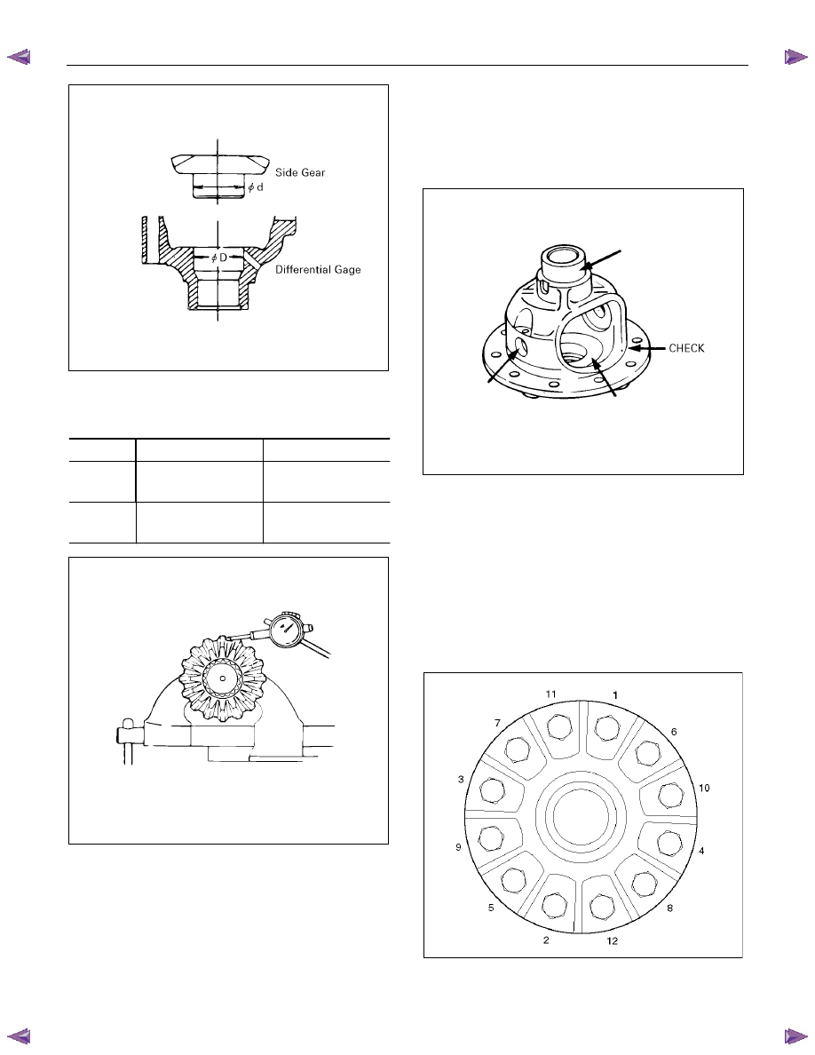
425R300010
Play in splines between the side gear and axle shafts.
mm(in)
Standard
Limit
φ220mm
0.08 - 0.38
(0.003 - 0.015)
0.5 (0.02)
φ194mm
0.08 - 0.36
(0.003 - 0.014)
0.5 (0.02)
425L100014
Differential cage
Check the ring gear the side gear fitting faces and the
cross pin hole for scores or roughness. Correct as
necessary. Slight scores or roughness may be
corrected with an oil stone or fine sand paper.
425R300006
Ring gear replacement:
1. The ring gear should always be replaced with the
drive pinion as a set.
2. Discard use bolts and install new ones.
3. Apply LOCTITE 271 on bolt from the end of
thread to the middle of straight portion.
4. Tighten the fixing bolts in a diagonal sequence as
illustrated.
Torque : 108 N
⋅m (11 kgf⋅m/80 lb⋅ft)
425RW033
REAR AXLE 4B-37
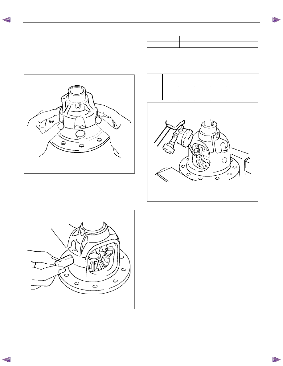
Reassembly
1. Install side gear with thrust washer in differential
cage.
2. Install the pinion gear by engaging it with the side
gears while turning both pinion gears
simultaneously in the same direction.
425RS048
3. Install cross pin.
• Be sure to install the cross pin so that it is in
alignment with the lock pin hole in the
differential cage.
425RS049
4. Check the amount of backlash.
Backlash between the side gear and the pinion
gear.
mm (in)
φ220mm 0.13-0.18
(0.005-0.007)
φ194mm 0.10-0.20
(0.004-0.008)
If the backlash is beyond the limits, adjust with a thrust
washer of selected thickness.
Thicknesses of thrust washers available.
Backlash mm
(in)
φ220
mm
0.80
(0.031)
0.90
(0.035)
1.00
(0.039)
1.10
(0.043)
1.20
(0.047)
1.30
(0.051)
φ194
mm
1.00
(0.039)
1.05
(0.041)
1.10
(0.043)
425RY00008
5. Install lock pin.
After lock pin installation, stake the case to
secure the lock pin.
6. Install ring gear.
Refer to “Ring gear replacement” on this section.
4B-38 REAR AXLE
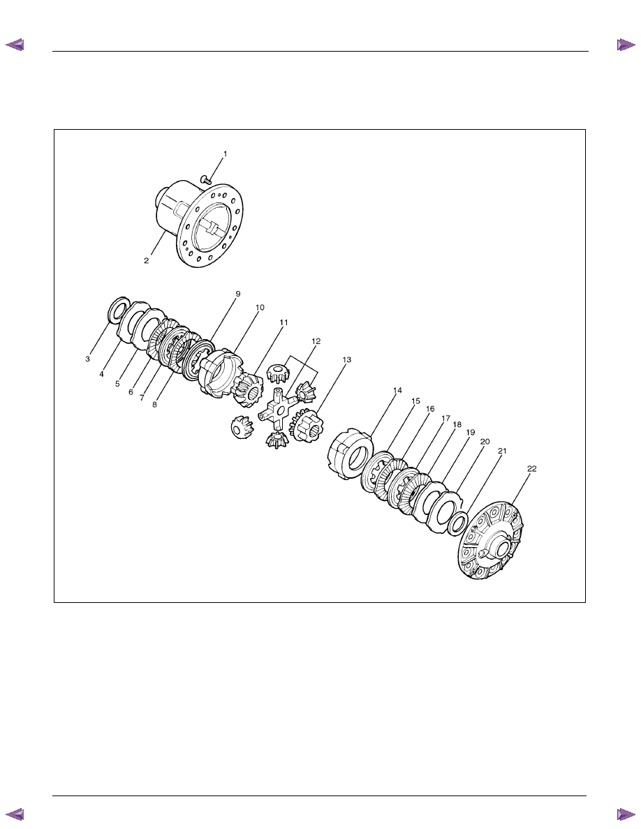
LIMITED SLIP DIFFERENTIAL (LSD)
Disassembled View
425R300007
Legend
1.
Screw
2. Differential Cage B
3.
Thrust
Washer
4.
Spring
Plate
5.
Spring
Plate
6.
Friction
plate
7.
Friction
disc
8.
Friction
plate
9.
Friction
disc
10.
Pressure
Ring
11.
Side
Gear
12. Pinion and Pinion Shaft
13.
Side
Gear
14.
Pressure
Ring
15.
Friction
Disc
16.
Friction
Plate
17.
Friction
Disc
18.
Friction
Plate
19.
Spring
Plate
20.
Spring
Plate
21.
Thrust
Washer
22. Differential Cage A
REAR AXLE 4B-39
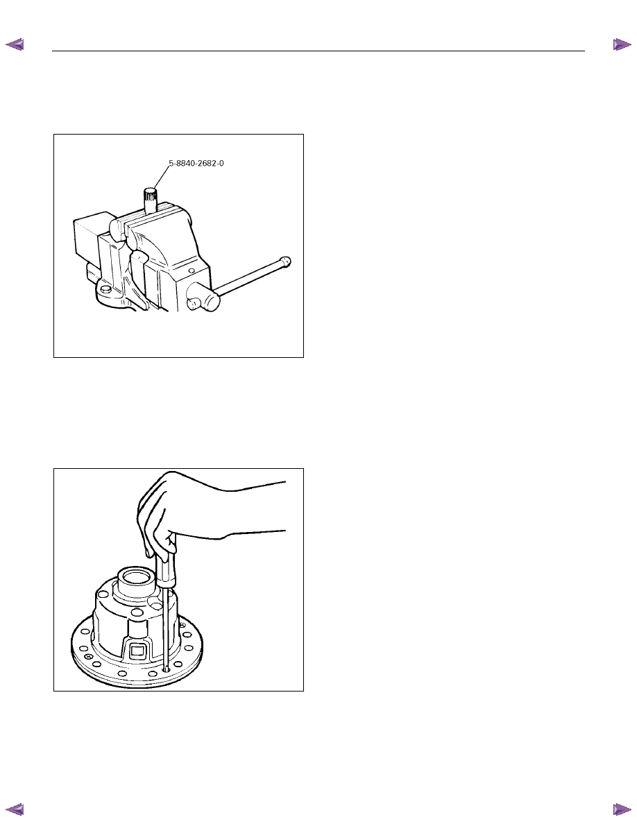
Disassembly
• Prepare a side gear holder : 5-8840-2682-0 as
shown in the left figure, clamp it with a stock vice,
and set a differential.
425R300008
1. Screw
• Apply a setting mark to the differential cage A
and differential cage B remove the bolt using
the press.
• Loosen four screws fixing differential cage A
to cage B equally and remove them.
425RS055
2. Remove differential cage A and B.
3. Remove thrust washer and two spring plates.
4. Remove friction plate and friction disc.
5. Remove friction plate and friction disc.
6. Remove pressure ring and side gear.
7. Remove pinion and pinion shaft.
8. Remove side gear and pressure ring.
9. Remove friction disc and friction plate.
10. Remove friction disc and friction plate.
11. Remove two spring plates and thrust washer.
Нет комментариевНе стесняйтесь поделиться с нами вашим ценным мнением.
Текст