Isuzu KB P190. Manual — part 135
4C1-36 FRONT WHEEL DRIVE
18. Bolt
Bolt Torque
N
⋅m (kgf⋅m/lb⋅ft)
98 (10.0/72)
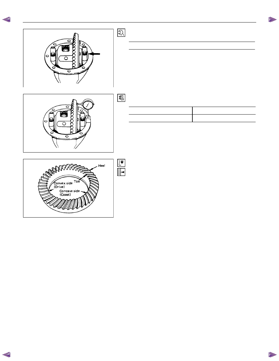
Measure the amount of run-out of the ring gear at its rear face.
mm(in)
Standard Limit
0.02 (0.001)
0.05 (0.002)
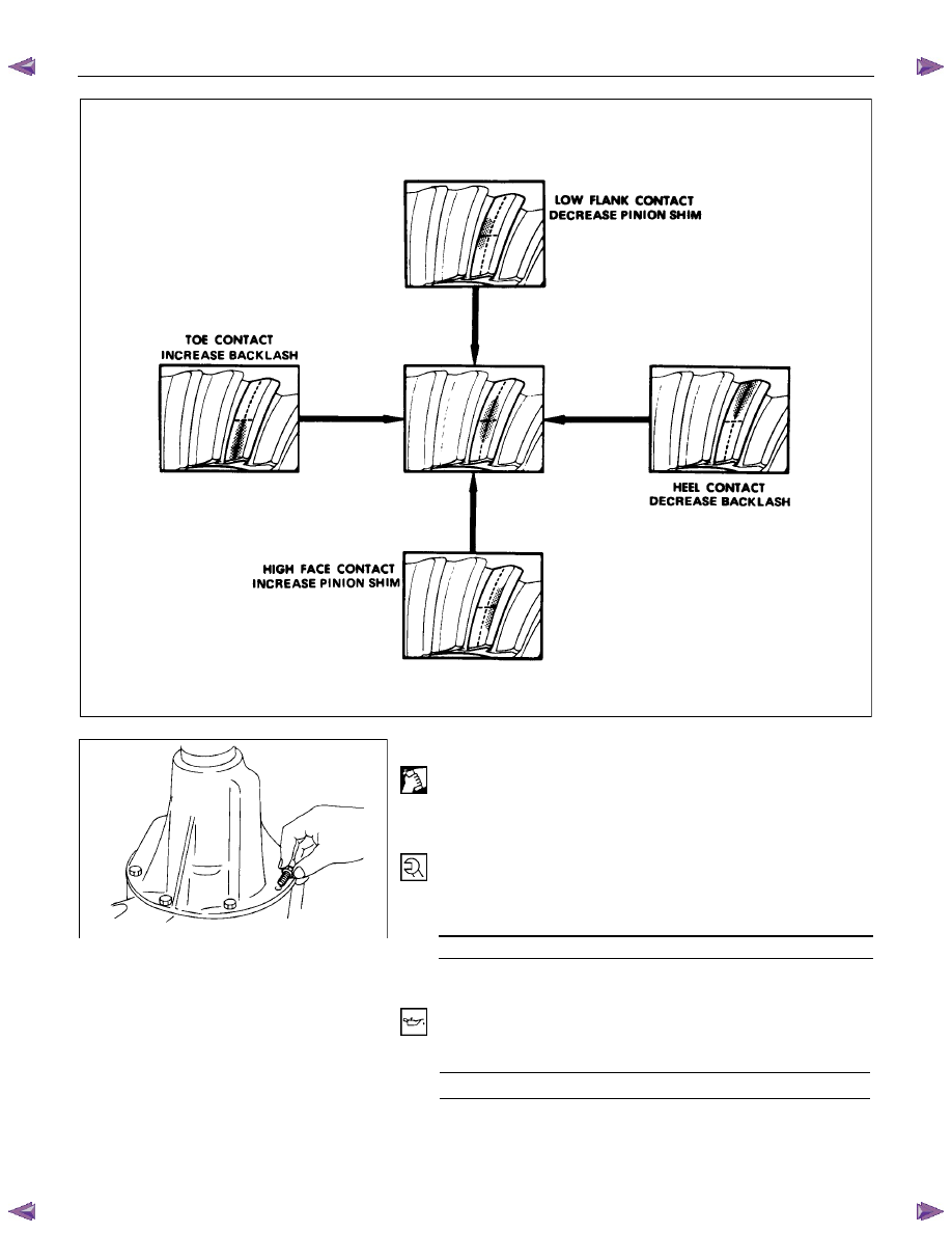
Gear Tooth Contact Pattern Check and Adjustment
Apply a thin coat of prussian blue or equivalent to the faces of
the 7 - 8 teeth of the ring gear. Check the impression of
contact on the ring gear teeth and make necessary adjustment
as described below if the contact is abnormal.
FRONT WHEEL DRIVE 4C1-37
20. Differential Assembly
(1) Clean the faces of the front axle case and differential
carrier.
Apply the recommended liquid gasket or its equivalent to
the sealing side of the axle case and the carrier.
(2) Attach the differential case and the carrier assembly to the
front axle case and tighten the nuts and bolts. The axle
case bolt is used for drainage.
Torque N
⋅m (kgf⋅m/lb⋅ft)
26 (2.7/20)
(3) Install the axle shaft assemblies as instructed earlier in this
section under “Axle Shaft Replacement”.
(4) Fill the axle case with hypoid gear lubricant, to just below
the filler hole.
Lubricant capacity
liter (US/UK gal)
1.4 (0.37/0.31)
4C1-38 FRONT WHEEL DRIVE
FRONT HUB AND DISC
(4×2 Except High Ride Suspension Model)
Disassembly
Refer to SECTION 3E “WHEELS AND TIRES” for wheel removal procedure.
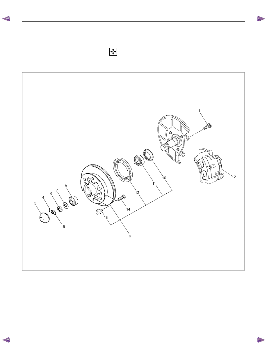
RTW34CLF000801
Disassembly Steps
1.
Bolt
▲ 2. Brake caliper
▲ 3. Hub cap
4.
Split
pin
5.
Nut
retainer
6.
Hub
nut
7.
Lock
washer
8.
Outer
bearing
▲ 9. Hub and disc assembly
10.
Oil
seal
11. Inner bearing and outer race
12. ABS sensor rotor
▲13. Bolt
▲14. Wheel pin
FRONT WHEEL DRIVE 4C1-39
Important Operations
Before removal, jack up the front of vehicle and support frame
with jack stands.
2. Brake Caliper
(1) Remove the two bolts from the rear side of the knuckle arm,
then remove the brake caliper, with the brake hose
attached.
(2) Use a wire etc., for attaching the brake caliper to the upper
link.
Refer to the section Brake.
3. Hub Cap
When removing hub cap, exercise care so as not to scratch or
distort hub fitting face.
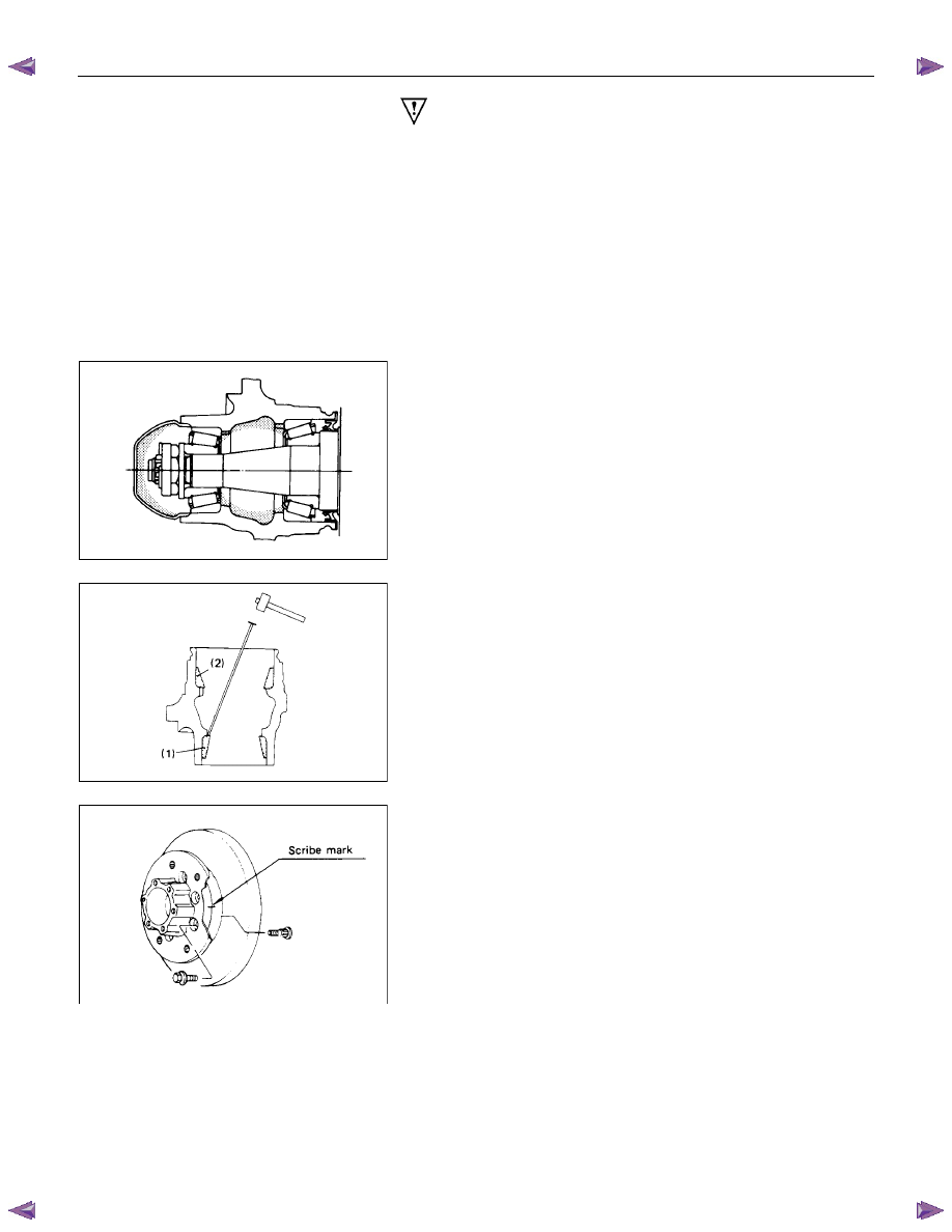
9. Hub and Disc Assembly
Using a brass bar to remove the outer bearing outer race (1),
oil seal, inner bearing and inner bearing outer race (2) from the
hug.
If necessary, replace the wheel pin in the following manner.
13. Bolt
14. Wheel Pin ; Front Hub
(1) Scribe mark on hub to disc before disassembly to insure
proper assembly.
(2) Drive out the ABS sensor rotor using a metal bar and
hammer through the two bolt holes.
• Discard the used ABS sensor rotor
Refer to the section Brake.
Нет комментариевНе стесняйтесь поделиться с нами вашим ценным мнением.
Текст