Isuzu KB P190. Manual — part 997

7A2-22 TRANSMISSION CONTROL SYSTEM (AW30–40LE)
Once the test vehicle has been identified an
“Application Menu” screen appears. Please select the
appropriate application.
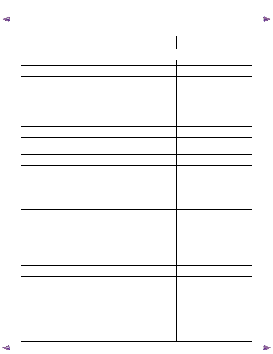
The following table shows, which functions are used for
the available equipment versions.
F0: Diagnostic Trouble Codes
F0: Read DTC Information
F1: Clear DTC Information
F1: Data Display
F2: Snapshot
F3: Actuator Test
F0: Solenoid 2-3 Test
F1: Solenoid 1-2/3-4 Test
F2: Pressure Control Solenoid (PCS)
F3: TCC Solenoid Test
F4: 3rd Start Lamp Test
F5: Power Lamp Test
F6: AT Oil Temperature Lamp Test
F7: Check Light Test
F4: Additional Functions
F0: Read ECU Identification
F5: Programming
F0: Program Vehicle Identification No.
TRANSMISSION CONTROL SYSTEM (AW30–40LE) 7A2-23
Diagnostic Trouble Codes
The purpose of the “Diagnostic Trouble Codes” mode is
to display stored TCM trouble codes.
When “Diagnostic Trouble Codes” is selected an
“Application Menu” screen appears.
Read DTC Information
When “Read DTC Information” is selected, an
“Application Menu” appears with a list of DTC
information function keys addressing DTC specifics and
their origins.
Function key selections may vary for particular vehicle
and/or system.
Requested emission-related DTCs
Clear DTC Information
The purpose of the “Clear DTC Information” mode is to
command the clearing of stored TCM trouble codes.
When “Clear DTC Information” is selected, a “Clear
DTC Information”, warning screen appears. This screen
informs you that by cleaning DTC's, “all stored DTC
information in controller will be erased”.
Do you want to clear DTC's (Yes/No).
Press either the Yes or No key when answering.
After clearing codes, confirm system operation by test-
driving the vehicle.
Allow the vehicle to shift through all four forward gears
in a manner which attempts to repeat the failure
condition.
NOTE: When the trouble has not been repaired and
the trouble code cannot be erased, check the vehicle
again.
Data Display
The purpose of the “Data Display” mode is to
continuously monitor data parameters.
The current actual values of all important sensors and
signals in the system are displayed through F1 mode.
When “Data Display” is selected an “Application Menu”
appears. “Transmission Data Display”.
See “Transmission Data” on next page.
Snapshot
When “Snapshot” is selected an “Application Menu”
appears.
When “Transmission Snapshot” application is selected
from the “Application Menu”, a “Snapshot Menu”
appears, displaying several options. “Snapshot” options
may vary from one system to another.
“Snapshot” allows a recording of all vehicle parameters.
There parameters may then be replayed at a future
point in time.
This action allows you to focus on making the condition
occur, rather than trying to view all of the data in
anticipation of the fault. The snapshot will collect
parameter information around a trigger point that you
select.
When a snapshot is taken, it is recorded onto the
PCMCIA memory card. When the Tech 2 is powered
down. Snapshots are not lost.
Actuator Test
The purpose of “Actuator Test” mode is to check for
correct operation of electronic system actuators.
Solenoid 2-3 Test, Solenoid 1-2/3-4 and Test TCC
Solenoid Test
You can operate the solenoids by pressing the “ON”
and “OFF” buttons.
Preconditions: P–N position, no vehicle speed, no
engine speed
Pressure Control Solenoid (PCS)
You can set desired PCS Current using the “ON” and
“OFF” button. The PCS Data informs about PCS
Current, Pressure and Duty Cycle.
Preconditions: P–N position, no engine speed, no
vehicle speed
3rd Start Lamp Test, Power Lamp Test, AT Oil
Temperature Lamp Test and Check Light Test
You can operate the lamps by pressing the “ON” and
“OFF” buttons.
Preconditions: none
NOTE:
Freeze Frame
Freeze Frame is an element of the Diagnostic
Management System which stores various vehicle
information at the moment an emission-related fault
is stored in memory and when the Check Trans
Lamp is commanded on. These data can help to
identity the cause of a fault. Refer to Storing And
Erasing Freeze Frame Data for more detailed
information.
7A2-24 TRANSMISSION CONTROL SYSTEM (AW30–40LE)
TRANSMISSION DATA
Scan Tool Parameter
Units Displayed
Typical Data Value at Engine Idle
Operating Conditions: Engine idling/ Engine coolant temperature is between 75 to 85
°C(167 to 185°F)/
Accelerator pedal is constant/ Neutral or Park/ Accessories OFF/ Vehicle located at sea level
Engine Coolant temperature
°C/°F
75 to 85
°C (167 to 185°F)
Engine Speed
RPM
700
Vehicle Speed
Km/h / MPH
0
Ignition Voltage
V
13.6
Accelerator Pedal Position Signal
%
0
Throttle Position
%
0
Accelerator Pedal Position Signal
During Cruise Control
% 0
Cruise Control
Inactive / Active
Inactive
Cruise Control OD Cancel Request
ON / OFF
OFF
Engine Warm Up Cycle Achieved
FALSE / TRUE
FALSE
Transmission Shift in Progress
Inactive / Active
Inactive
Garage Shift Control
Inactive / Active
Inactive
MIL Request Command
ON / OFF
OFF
Transmission Check Light
ON / OFF
OFF
Transmission Oil Temperature Lamp
ON / OFF
OFF
Power Drive Lamp
ON / OFF
OFF
3rd Start Lamp
ON / OFF
OFF
Transmission Fluid Temperature
°C/°F
70 to 80
°C (158 to 176°F)
AT Input Speed
RPM
625
AT Output Speed
RPM
0
Transmission Range
Park / Reverse /
Neutral / Drive 4 /
Drive 3 / Drive 2 /
Drive 1
Park
TR Switch P
ON / OFF
ON
TR Switch R
ON / OFF
OFF
TR Switch N
ON / OFF
OFF
TR Switch D
ON / OFF
OFF
TR Switch 3
ON / OFF
OFF
TR Switch 2
ON / OFF
OFF
TR Switch L
ON / OFF
OFF
Diagnostic Switch
Open / Close
Open
Brake Pedal Switch
ON / OFF
OFF
Power Drive Switch
ON / OFF
OFF
3rd Start Switch
ON / OFF
OFF
4 Wheel Drive Low
ON / OFF
OFF
Shift Solenoid 1 Command
ON / OFF
ON
Shift Solenoid 2 Command
ON / OFF
OFF
TCC Solenoid
Engaged / Disengaged
Disengaged
Downhill Mode
Inactive / Active
Inactive
Active Shift Mode
Normal Mode /
Power Mode /
3rd Gear Start /
Transfer 4L MODE
Hot 1 / Hot 2 /
UPHILL MODE 1 /
UPHILL MODE 2 /
Cruise MODE /
Warm Up MODE
Normal Mode
Estimated Gear Ratio
:1
7.97 : 1

TRANSMISSION CONTROL SYSTEM (AW30–40LE) 7A2-25
Scan Tool Parameter
Units Displayed
Typical Data Value at Engine Idle
Desired PCS Pressure
kPa
32.0
Current Gear
Neutral / 1st / 2nd /
2nd L-Up / 3rd /
3rd L-Up / 4th /
4th L-Up
1st
Command Gear
Neutral / 1st / 2nd /
2nd L-Up / 3rd /
3rd L-Up / 4th /
4th L-Up
1st
PCS Desired Current
mA
976
PCS Actual Current
mA
976
Speed Ratio
0.89 : 1
TCC Slip Speed
rpm
75
Нет комментариевНе стесняйтесь поделиться с нами вашим ценным мнением.
Текст