Isuzu KB P190. Manual — part 586
6E–174
ENGINE DRIVEABILITY AND EMISSIONS
DIAGNOSTIC TROUBLE CODE (DTC) P0325 KNOCK SENSOR (KS) MODULE
CIRCUIT
Condition for setting the DTC and action taken when the DTC sets
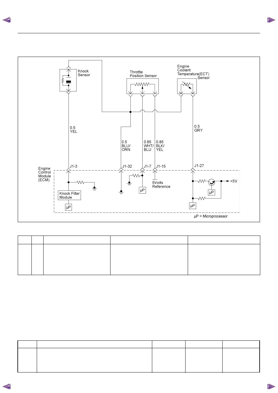
Circuit Description
The knock sensor (KS) system is used to detect engine
detonation. The knock sensor produced an AC voltage
signal. The knock sensor sends this signal to the ECM.
The amplitude and the frequency of the AC voltage
signal depends upon the knock level being detected.
The ECM will then retard the spark timing based on the
signals from the Knock Sensor.
Diagnostic Aids
Correct any abnormal engine noise before using the
diagnostic table.
Check for an open circuit.
Diagnostic Trouble Code (DTC) P0325 Knock Sensor Module Circuit
Code
Type
DTC Name
DTC Setting Condition
Fail-Safe (Back Up)
P0325
B
Knock Sensor Module Circuit
1. No DTC relating to MAP sensor.
2. Engine coolant temperature is more than
50 deg. C.
3. Engine speed is more than 1600rpm.
4. Knock sensor filter module integrated cir-
cuit malfunction.
ECM retards ignition timing 4 deg. C.
Step
Action
Value(s)
Yes
No
1
Was the “On-Board Diagnostic (OBD) System Check”
performed?
—
Go to Step 2
Go to On Board
Diagnostic
(OBD) System
Check
ENGINE DRIVEABILITY AND EMISSIONS
6E–175
2
1. Connect the Tech 2.
2. Review and record the failure information.
3. Select “F0: Read DTC Infor By Priority” in “F0:
Diagnostic Trouble Code”.
Is the DTC P0325 stored as “Present Failure”?
—
Go to Step 3
Refer to
Diagnostic Aids
and Go to Step
3
3
1. Using the Tech2, ignition “On” and engine “Off”.
2. Select “Clear DTC Information” with the Tech2 and
clear the DTC information.
3. Operate the vehicle and monitor the “F5: Failed
This Ignition” in “F2: DTC Information”.
Was the DTC P0325 stored in this ignition cycle?
—
Go to Step 4
Refer to
Diagnostic Aids
and Go to Step
4
4
Check for poor/faulty connection at the knock sensor
or ECM connector. If a poor/faulty connection is found,
repair as necessary.
Was the problem found?
—
Verify repair
Go to Step 5
5
Visually check the knock sensor.
Was the problem found?
—
Go to Step 10
Go to Step 6
6
Listen to the engine noise while raising and lowering
the engine speed.
Is a knock or audible noise present?
—
Go to Step 7
Go to Step 8
7
Repair the mechanical engine problem or a loose
bracket or component.
Is the action complete?
—
Verify repair
—
Step
Action
Value(s)
Yes
No
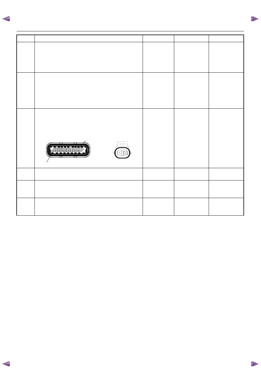
32
3
E-60(J1)
E-84
6E–176
ENGINE DRIVEABILITY AND EMISSIONS
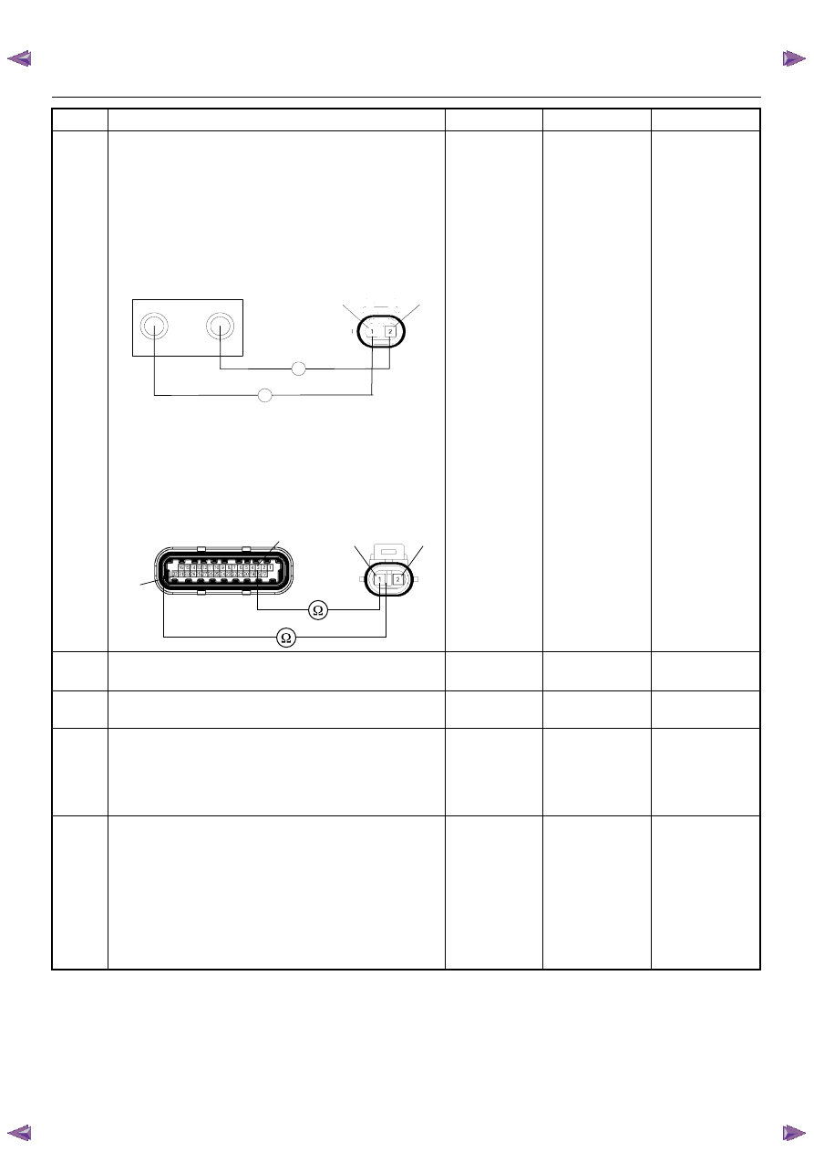
8
Using the DVM and check the knock sensor circuit.
Breaker box is available:
1. Ignition “Off”, engine “Off”.
2. Install the breaker box as type A. (ECM
disconnected) Refer to 6E-88 page.
3. Disconnect the knock sensor.
4. Check the circuit for open circuit.
Was the problem found?
Breaker box is not available:
1. Ignition “Off”, engine “Off”.
2. Disconnect the knock sensor connector and ECM
connector.
3. Check the circuit for open circuit.
Was the problem found?
—
Repair faulty
harness and
verify repair
Go to Step 9
9
Substitute a known good knock sensor and recheck.
Was the problem solved?
—
Go to Step 10
Go to Step 11
10
Replace the knock sensor.
Was the problem solved?
—
Verify repair
Go to Step 11
11
Is the ECM programmed with the latest software
release?
If not, download the latest software to the ECM using
the “SPS (Service Programming System)”.
Was the problem solved?
—
Verify repair
Go to Step 12
12
Replace the ECM.
Is the action complete?
IMPORTANT: The replacement ECM must be
programmed. Refer to section of the Service
Programming System (SPS) in this manual.
Following ECM programming, the immobilizer system
(if equipped) must be linked to the ECM. Refer to
section 11 “Immobilizer System-ECM replacement” for
the ECM/Immobilizer linking procedure.
—
Verify repair
—
Step
Action
Value(s)
Yes
No
J1-3
J1-32
Breaker Box
E-84
2
1
Ω
Ω
3
E-60(J1)
E-84
32
2
1
ENGINE DRIVEABILITY AND EMISSIONS
6E–177
DIAGNOSTIC TROUBLE CODE (DTC) P0327 KNOCK SENSOR (KS) CIRCUIT
Condition for setting the DTC and action taken when the DTC sets
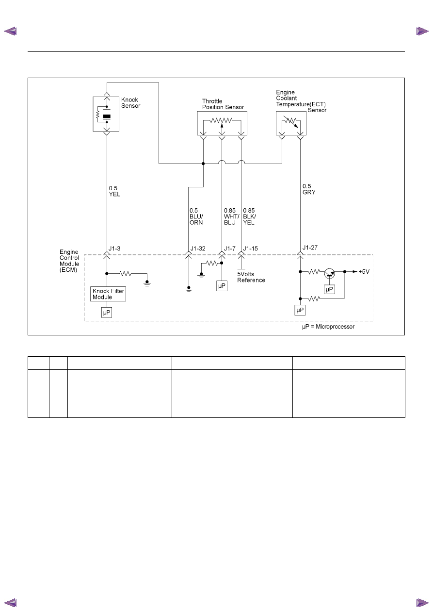
Circuit Description
The ECM uses the Knock Sensor (KS) in order to detect
engine detonation. This allows the ECM to retard the
Ignition Control (IC) spark timing based on the KS signal
the ECM receives. The knock sensors produce an AC
signal that rides on the 1.3 volts DC. The signal’s
amplitude and frequency are dependent upon the
amount of the knock being experienced.
The ECM determines whether the knock is occurring by
comparing the signal level on the KS circuit with a
voltage level on the noise channel. The normal engine
noise varies depending on the engine speed and load.
Then the ECM determines that an abnormally high
noise channel voltage level is being experienced, a
Diagnostic Trouble Code P0327 sets.
Diagnostic Aids
Check for the following conditions:
A poor connection at the ECM. Inspect the knock
sensor and the ECM connectors for: , broken locks,
improperly formed or damaged terminals.
• Backed out terminals
• Broken locks
• Improperly formed or damaged terminals
Also, check the wiring harness for: shorts to ground,
shorts to battery positive, and open circuits.
• A misrouted harness. Inspect the knock sensor
harness in order to ensure that it is not routed too
close to high voltage wires such as spark plug leads.
Code
Type
DTC Name
DTC Setting Condition
Fail-Safe (Back Up)
P0327
A
Knock Sensor Circuit
1. No DTC relating to MAP sensor.
2. Engine coolant temperature is more than
50 deg. C.
3. Engine speed is more than 1600rpm.
4. Knock sensor harness short to ground or
short to voltage circuit.
ECM retards ignition timing 4 deg. C.
Нет комментариевНе стесняйтесь поделиться с нами вашим ценным мнением.
Текст