Isuzu KB P190. Manual — part 942
Automatic Transmission – 4L60E – General Information
Page 7C1–8
2.4 System
Protection
Devices
Should 1st gear be selected and left in that range, the TCM will protect the engine from an over-speeding condition by
upshifting to 2nd gear at a pre-determined point. Similarly, the TCM provides high speed, downshift protection by
preventing a manual shift into 1st gear above pre-determined engine speeds.
Under severe operating conditions such as towing in high ambient temperatures, fluid temperatures can rise to a point
where lubrication breakdown can occur. In addition to having an oil cooler fitted to the vehicle, the 4L60E transmission is
also fitted with a transmission fluid temperature sensor located in the Transmission Range (TR) Pressure Switch
Assembly (PSA).
When fluid temperatures in excess of 135
°C are sensed, the torque converter clutch is applied as programmed, in 3rd or
4th gear. This action reduces further the fluid temperature during normal operation of the torque converter. While these
high fluid temperatures are sensed however, torque converter clutch apply is not available when the throttle opening is
above 50%.
Similarly, when the fluid temperature is below 29
°C, the TCM prevents torque converter clutch apply.
If a condition occurs, preventing electronic control of the transmission's functions, a 'Fail Safe' mode will default the
transmission to 3rd gear when either Drive or 3 is selected, applying also maximum line pressure. While in this mode, the
vehicle operator can still manually select 2, 1, Reverse, Park or Neutral, should the need arise.
2.5 Self
Diagnosis
If any transmission operation controlled by the TCM begins to operate outside its pre-set parameters, the TCM has the
ability to store a range of diagnostic codes which can be accessed by the servicing technician, thereby localising the
problem.
2.6
TCM Sensors and Actuators
As indicated earlier, there are a number of sensors and switches providing input information for the TCM programming
that will allow the TCM to change the shift pattern, shift feel and torque converter clutch operation.
The TCM does this by comparing this input information with its predetermined values on shift pattern, fluid pressure
maps, shift duration parameters, extreme heat protection programming and adaptive controls.
In addition, each input signal and output actuator operation is also monitored and if outside its pre-set parameters, a
diagnostic code is logged for future reference by the servicing technician.
Automatic Transmission – 4L60E – General Information
Page 7C1–9
3
Transmission Control Module
Operation Overview
3.1
Transmission Control Module
With the introduction of the new HFV6 engine, the powertrain architecture has been redesigned to accommodate this
introduction. With this design, a new bus architecture and protocol has also been introduced. The new bus connects the
following modules:
•
engine control module (ECM),
•
transmission control module (TCM),
•
powertrain interface module (PIM) and
•
ABS module.
The protocol used to communicate between these modules is called General Motors Local Area Network (GM LAN)
which is based on Controller Area Network (CAN) communication protocol. For further information on GM LAN protocol
and data bus structure, refer to 6E1 Powertrain Interface Module – V6.
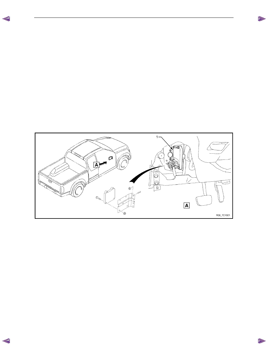
Component Location
The TCM (1) is located under the instrument panel, it is attached to a bracket mounted to the firewall as shown in
Figure 7C1 – 2.
For the other components using the GM LAN databus, refer to 6E1 Powertrain Interface Module – V6.
Figure 7C1 – 2
Transmission Control Module Data Transfer
The TCM uses various information to control the shift of the transmission. Besides the direct inputs from the various
transmission sensors directly into the TCM, the TCM uses data from the GM LAN databus.
The inputs/outputs directly connected to the TCM from the transmission are:
•
shift solenoids,
•
torque converter clutch control,
•
pressure control solenoid,
•
transmission fluid temperature sensor and
•
vehicle speed sensor.
Refer to 3.2
TCM Wiring Diagrams.
The transmission also receives inputs from the park/neutral position and back up lamp switch assembly.
The TCM needs other various data parameters to control the transmission correctly. These include throttle plate angle,
whether cruise control is engaged and active or not, engine RPM etc. These are provided to the TCM from the ECM via
serial data using GM LAN communication protocol.
The TCM also supplies information that is used by other components and systems within the vehicle such as the engine
control module (ECM) and instrument cluster. Any information that is required on the body side of the data bus (UART
protocol) is translated by the powertrain interface module (PIM). For further information on the data bus structure, the
PIM and its operation, refer to 6E1 Powertrain Interface Module – V6.
Automatic Transmission – 4L60E – General Information
Page 7C1–10
Transmission Control Module Operation
The TCM processes data every 10 milliseconds from various sensors, such as throttle position, vehicle speed, gear
range, temperature, engine load and other inputs. The TCM compares all its various inputs with the internal programming
and calibration of the TCM using this data, a signal is transmitted to the valve body shift solenoids, which activate the
shift valves for precise shift control. Shift points are therefore precisely controlled and are identical from vehicle to vehicle.
The TCM also control torque converter clutch apply and release.
Shift feel is also electronically controlled by the TCM, by signals sent to the variable force solenoid, which controls fluid
line pressure and it is this pressure that precisely determines how the shifts will feel. In this way, the TCM electronically
synchronises the engine and transmission into a single integrated powertrain system for optimum performance, shift
timing, fuel efficiency and emission control.
3.2 TCM
Wiring
Diagrams
For details of the transmission control module (TCM) wiring diagrams, refer to 8A Electrical-Body and Chassis.

Automatic Transmission – 4L60E – General Information
Page 7C1–11
4 Transmission
Definitions
and
Abbreviations
The following definitions and abbreviations are provided to establish a common language and assist the user in
describing transmission related conditions. The use of these terms and/or conditions can be found in the various parts of
the automatic transmission sections, but more particularly in 7C3 Automatic Transmission – 4L60E – Hydraulic and
Mechanical Diagnosis.
4.1
Throttle Position Related Definitions
Throttle Position
Definition
Minimum Throttle
The least amount of throttle opening required for an upshift.
Light Throttle
Approximately 1/4 of accelerator pedal travel (25% Throttle Position).
Medium Throttle
Approximately 1/2 of accelerator pedal travel (50% Throttle Position).
Heavy Throttle
Approximately 3/4 of accelerator pedal travel (75% Throttle Position).
Wide Open Throttle (WOT)
Full travel of the accelerator pedal (100% Throttle Position).
Full Throttle Detent Downshift
A quick apply of the accelerator pedal to its full travel, forcing a downshift.
Zero Throttle Coast Down
A full release of the accelerator pedal while the car is in motion and in drive range.
Engine Braking
A condition where the engine is used to slow the car by manually downshifting
during a zero throttle coast down.
4.2
Noise Condition Related Definitions
Noise Condition
Definition
Planetary Gear Noise
A whine related to car speed most noticeable in first gear or reverse. Becomes less
noticeable after an upshift.
Pump Noise
A high pitch whine increasing with engine r.p.m.
4.3 General
Definitions
General Definition
Accumulator
A component of the transmission that absorbs hydraulic pressure during the apply of a
clutch or band. Accumulators are designed to control the quality of a shift from one
gear range to another.
Adaptive Learning
Programming within the TCM that automatically adjusts hydraulic pressures in order to
compensate for changes in the transmission (i.e. component wear).
Applied
An 'Applied Component' is holding another component to which it is splined or
assembled to. Also referred to as "engaged".
Apply Components
Hydraulically operated clutches, servo’s, bands and mechanical one-way roller or
sprag clutches that drive or hold members of a planetary gear set.
Apply Plate
A steel clutch plate in a clutch pack, located next to the (apply) piston.
Backing Plate
A steel plate in a clutch pack that is usually the last plate in that clutch assembly
(furthest from the clutch piston).
Band
An apply component that consists of a flexible strip of steel and friction material that
wraps around a drum. When applied, it tightens around the drum and prevents the
drum from rotating.
Brake Switch
An electrical device that provides signals to the transmission control module (TCM),
based on the position of the brake pedal. The TCM uses this information to apply or
release the torque converter clutch (TCC).
Centrifugal Force
A force that is imparted on an object (due to rotation) that increases as that object
moves further away from a centre-point of rotation.
Нет комментариевНе стесняйтесь поделиться с нами вашим ценным мнением.
Текст