Isuzu KB P190. Manual — part 941
Automatic Transmission – 4L60E – General Information
Page 7C1–4
1.2
7C1 Automatic Transmission – 4L60E –
General Information
This section provides general information about the automatic transmission, including:
•
A glossary of terms,
•
Transmission identification information,
•
Electrical overview of the Transmission Control Module (TCM),
•
Some notes that address safe workshop practices,
•
Service notes relating to fasteners and consumable items used at various stages throughout this section,
•
Special tools required to work on the transmission,
•
Fastener torque specifications, and
•
Transmission specifications.
For all information relating to the mechanical construction and function of the 4L60E automatic transmission, refer to the
General Motors Powertrain Group Electronically Controlled Automatic Transmission Technician’s Guide.
This guide includes such information as:
•
Transmission Cutaway Views,
•
Principles of Operation,
•
Power Flow,
•
Complete Hydraulic Circuits,
•
Bushing and Bearing Locations,
•
Seal Locations and
•
Illustrated Parts List.
N O T E
Specifications quoted in this General Motors
Powertrain Group Electronically Controlled
Automatic Transmission Technician Guide may
not be for the vehicle you are working on. For
correct specifications refer to
7 Transmission
Specifications.
Recommendations
When servicing the transmission, all parts should be cleaned and inspected. Individual units should be reassembled
before disassembly of other units to avoid confusion and interchanging of parts.
a
Thoroughly clean the transmission exterior before removal of any component.
b
Disassembly and reassembly must be made on a clean work bench. Cleanliness is of the utmost importance, the
bench tools and parts must be kept clean at all times.
c
Before installing screws and other fasteners into aluminium parts, dip screw threads into transmission fluid to
prevent galling aluminium threads and to prevent screws from seizing.
d
To prevent thread stripping, always use a torque wrench when installing screws or nuts.
e
If threads in aluminium parts are stripped or damaged, the parts can be made serviceable by the use of
commercially available thread inserts.
f
Protective tools must be used when assembling seals to prevent damage. The slightest flaw in the sealing surface
of the seal can cause an oil leak.
g
Aluminium castings and valve parts are very susceptible to nicks, burrs, etc. and should be handled with care.
h
Expand Internal snap rings and compress external snap rings if they are to be re-used to ensure proper seating
when reinstalled.
i
Do not re-use removed O-rings, gaskets and oil seals.
j
Teflon oil seal rings should not be removed unless damaged.
k
During assembly of each unit, all internal moving parts must be lubricated with transmission fluid.
Oil Cooler Pipes
Should any transmission fluid cooling pipe suffer accidental damage, a genuine replacement pipe must be fitted. Refer to
the current release of PartFinder™ to determine the correct part number for the particular engine and pipe involved.
Reworking of damaged pipes or hand made replacements are not permitted.

Automatic Transmission – 4L60E – General Information
Page 7C1–5
Clean and Inspect
Do not use solvents on neoprene seals,
composition faced clutch plates or thrust
washers as damage to parts may occur.
After complete disassembly of a component, wash all metal parts in a clean solvent and dry with compressed air. Blow
oil passages out and check to make sure they are not obstructed, small passages should be checked with tag wire. All
parts should be inspected to determine if replacement is required.
Pay particular attention to the following:
•
Inspect linkage and pivot points for excessive wear.
•
Bearing and thrust surfaces of all parts should be checked for excessive wear and scoring.
•
Check for broken seal rings, damaged ring lands and damaged threads.
•
Inspect seals for damage.
•
Mating surfaces of castings should be checked for burrs. Irregularities may be removed by lapping the surface with
emery paper laid on a flat surface, such as a piece of plate glass.
•
Castings should be checked for cracks and porosity.
1.3
7C2 Automatic Transmission – 4L60E –
Electrical Diagnosis
For transmissions fitted to V6 engines, the electrical diagnosis is in this Section. A new electrical circuit and control
module has been introduced for automatic transmissions fitted to the V6 engines.
1.4
7C3 Automatic Transmission – 4L60E –
Hydraulic and Mechanical Diagnosis
Information contained in 7C3 Automatic Transmission – 4L60E – Hydraulic and Mechanical Diagnosis will assist in the
diagnosis of the mechanical and hydraulic components in the 4L60E automatic transmission, while the transmission
remains installed on the vehicle.
Examples of the type of diagnostic information contained within this section are:
•
transmission functional test,
•
line pressure information,
•
transmission fluid diagnosis,
•
symptom diagnosis and
•
shift speed charts.
1.5
7C4 Automatic Transmission – 4L60E –
On-vehicle Servicing
Information in 7C4 Automatic Transmission – 4L60E – On-vehicle Servicing covers transmission fluid level checking, as
well as specific information for servicing some components while the transmission remains installed on the vehicle. This
Section also covers the transmission removal and reinstallation to the vehicle.
Automatic Transmission – 4L60E – General Information
Page 7C1–6
2 General
information
The hydra-matic 4L60E automatic transmission is fitted to vehicles with HFV6 engine. The mechanical and internal
electrical operation of the transmission unit is controlled by the transmission control module (TCM) for HFV6 engine.
•
For information on the mechanical operation of the transmission, refer to General Motors Powertrain Group
Electronically Controlled Automatic Transmission Technician's Guide.
•
For further information on the TCM, refer to 3.1 Transmission Control Module.
2.1
Transmission Control Module – HFV6
Vehicles fitted with a V6 engine and the 4L60E transmission have a new control module and data bus architecture from
previous models. This is due to the introduction of the new V6 engine. Mechanically, the transmission has not changed.
V6 equipped vehicles are now fitted with T42 – Delphi with GMPT software, transmission control module (TCM) to
control all transmission operations. For further information on the TCM and its operation, refer to 3 Transmission Control
Module Operation Overview.
2.2 Transmission
Identification
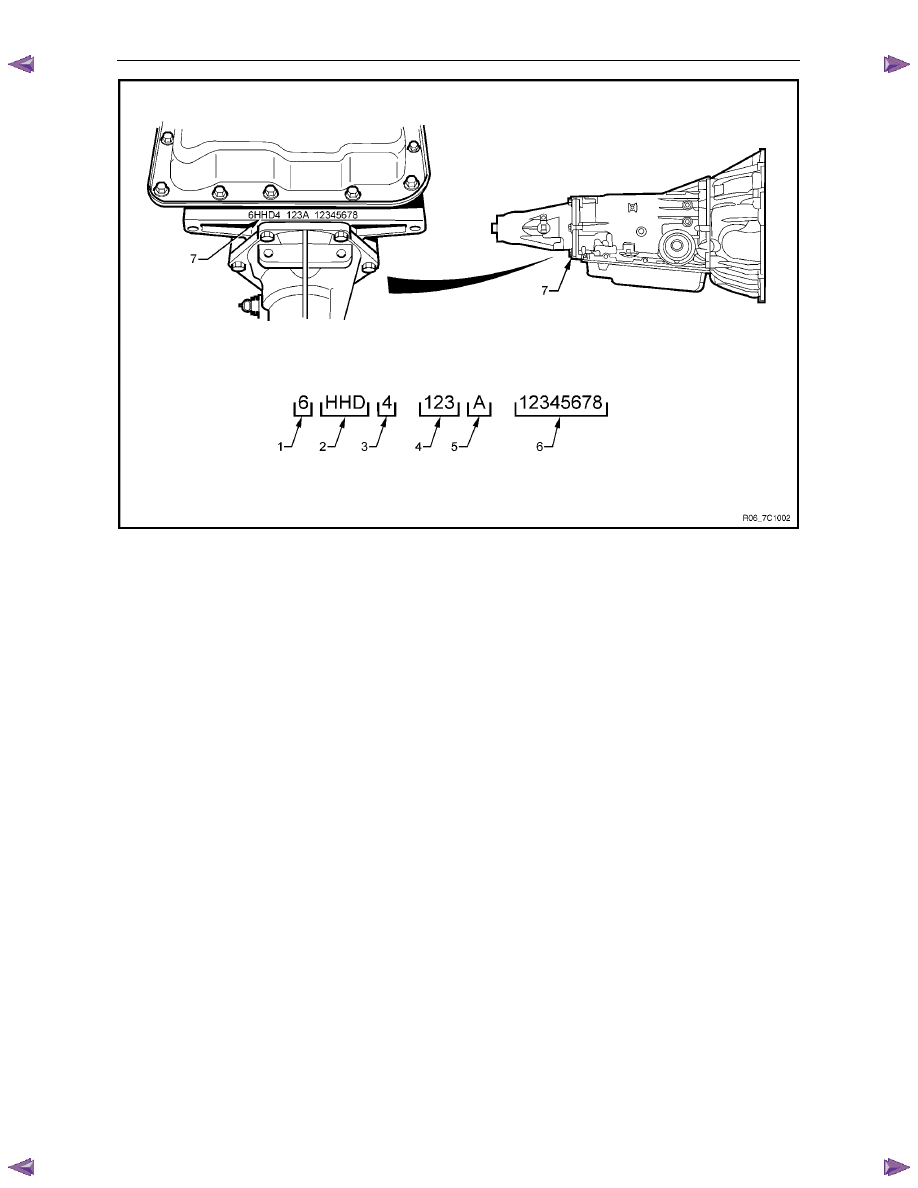
The 4L60E automatic transmission application and identification can be determined from the stamping at the rear of the
transmission , in the location (7) as shown in Figure 7C1 – 1.
Identification is as follows:
(1) model year,
•
(6 = 2006).
(2) Broad Cast Code Identifier,
•
HHD = RWD – 3.6 litre HFV6
•
HLD = 4WD – 3.6 litre HFV6
(D = model 4L60E).
(3) Manufacturer Source Code,
•
(4 = Ramos).
(4) Julian date (day of the year).
(5) Shift Build,
•
'A','B','J' = First shift,
•
'C','H','W' = Second shift.
(6) Individual transmission serial number.
Automatic Transmission – 4L60E – General Information
Page 7C1–7
Figure 7C1 – 1
Legend
1 Model
year
2
Broad Cast Code Identifier
3
Manufacturer Source Code
4 Julian
Date
5 Shift
Build
6
Individual Transmission Serial Number
7
Identification Stamping Location
2.3
Economy, Power and Cruise Modes
The programming in the transmission control module (TCM) allows for different shift patterns, which are driver
controllable through the use of the power (PWR) button. The power button is located in the centre console.
Economy Mode
The calibration for this mode is for maximum comfort, with minimal intrusion of engine noise and smooth shifts under all
driving conditions. When additional power is required for acceleration, full throttle upshifts are similar to those calibrated
for the power mode.
Power Mode
When activated, the TCM modifies the transmission calibration in the following ways:
1
When the throttle is less than 80% open, later upshift points are provided.
2
Shift time is reduced.
3
The torque converter clutch (TCC) will be applied in both the third and fourth speed ranges.
Cruise Mode
When the driver activates the cruise control (where fitted), the power icon in the instrument clusters multi-function display
(MFD) will be deactivated (provided the vehicle was operating in power mode) and the transmission shift pattern will
switch to the cruise control pattern. When in this mode, the TCM modifies the shift pattern so that earlier downshift and
later upshift points are provided.
Through the electronic programming of the logic processes contained in the TCM, the frequency of gear shifting and
torque converter clutch application and release is minimised. The end result of these logic processes, is that a quick
series of upshifts and downshifts (e.g. a '4 – 3 – 4' shift pattern) is minimised.
Нет комментариевНе стесняйтесь поделиться с нами вашим ценным мнением.
Текст