Isuzu KB P190. Manual — part 380
6A-160 ENGINE MECHANICAL (4JK1/4JJ1)
• Install the gasket in the slot of the gear case
cover.
• Tighten the bolts to the specified torque.
Tightening torque: 8 N
⋅⋅⋅⋅m (0.8 kg⋅⋅⋅⋅m / 69 lb in)
RTW56ASH012101
3. Install the crank pulley.
• Tighten the bolts to the specified torque.
Tightening torque: 294 N
⋅⋅⋅⋅m (30.0 kg⋅⋅⋅⋅m / 217 lb ft)
4. Install the noise cover to the timing chain cover
lower.
• Tighten the bolts to the specified torque.
Tightening torque: 10 N
⋅⋅⋅⋅m (1.0 kg⋅⋅⋅⋅m / 87 lb in)
5. Install the vacuum pump.
• Tighten the nuts to the specified torque.
Tightening torque: 25 N
⋅⋅⋅⋅m (2.5 kg⋅⋅⋅⋅m / 18 lb ft)
• Install the oil pipe (feed side and return side) of
vacuum pump.
• Install the vacuum pipe bracket and vacuum
pipe.
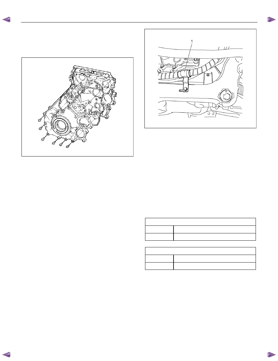
6. Install the power steering pump.
• Tighten the nuts to the specified torque.
Tightening torque: 25 N
⋅⋅⋅⋅m (2.5 kg⋅⋅⋅⋅m / 18 lb ft)
• Install the bracket of power steering oil hose
clip (1).
LTW56ASH000101
7. Install the lower fan shroud.
8. Install the fan drive belt and pulley.
• Install the fan drive belt with the fan pulley.
9. Install the fan and fan clutch.
• Tighten the bolts to the specified torque.
Tightening torque: 8 N
⋅⋅⋅⋅m (0.8 kg⋅⋅⋅⋅m / 69 lb in)
10. Adjust the drive belt of generator and A/C
compressor.
• Apply tension to the fan drive belt by moving
the generator.
• Apply a force of 98 N (10 kg / 22 lb) to the drive
belt mid portion to check the drive belt
deflection.
Generator drive belt deflection
mm (in)
New belt
5 - 6 (0.20 – 0.24)
Reuse belt
7 - 8 (0.28 – 0.31)
A/C compressor drive belt deflection
mm (in)
New belt
6 - 7 (0.24 – 0.28)
Reuse belt
8 - 9 (0.31 – 0.35)
11. Install the upper fan shroud.
12. Install the radiator upper hose.
13. Replenish the engine coolant.
ENGINE MECHANICAL (4JK1/4JJ1) 6A-161
Oil Pressure SW
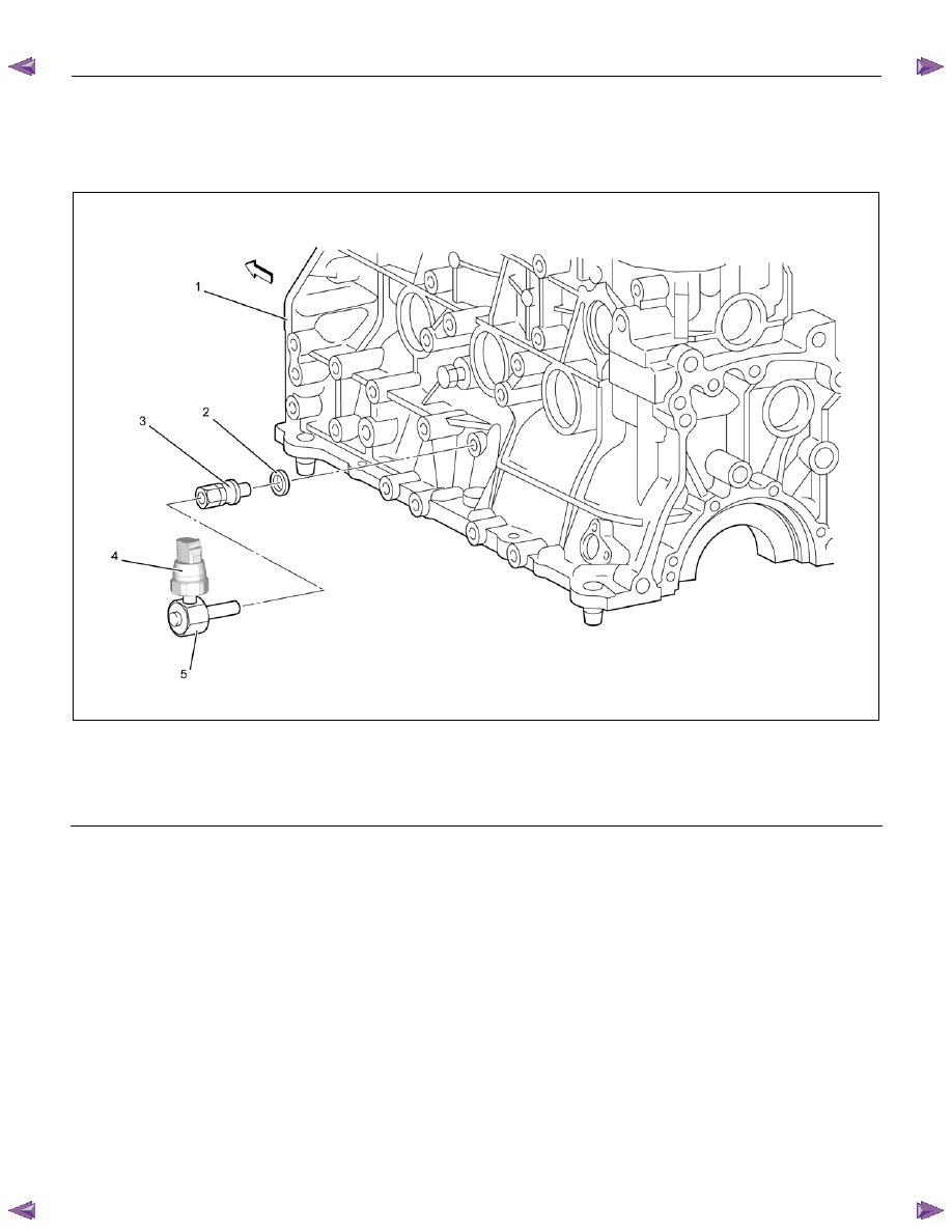
Components
RTW76AMF000401
Legend
1. Cylinder
Block
2. Gasket
3. Nipple; Oil Pressure Warning SW
4. Oil Pressure SW
5. Nipple; Oil Gallery
6A-162 ENGINE MECHANICAL (4JK1/4JJ1)
Removal
1. Remove the oil pressure SW.
2. Remove the nipple; oil gallery.
3. Remove the nipple; oil pressure warning SW and
gasket.
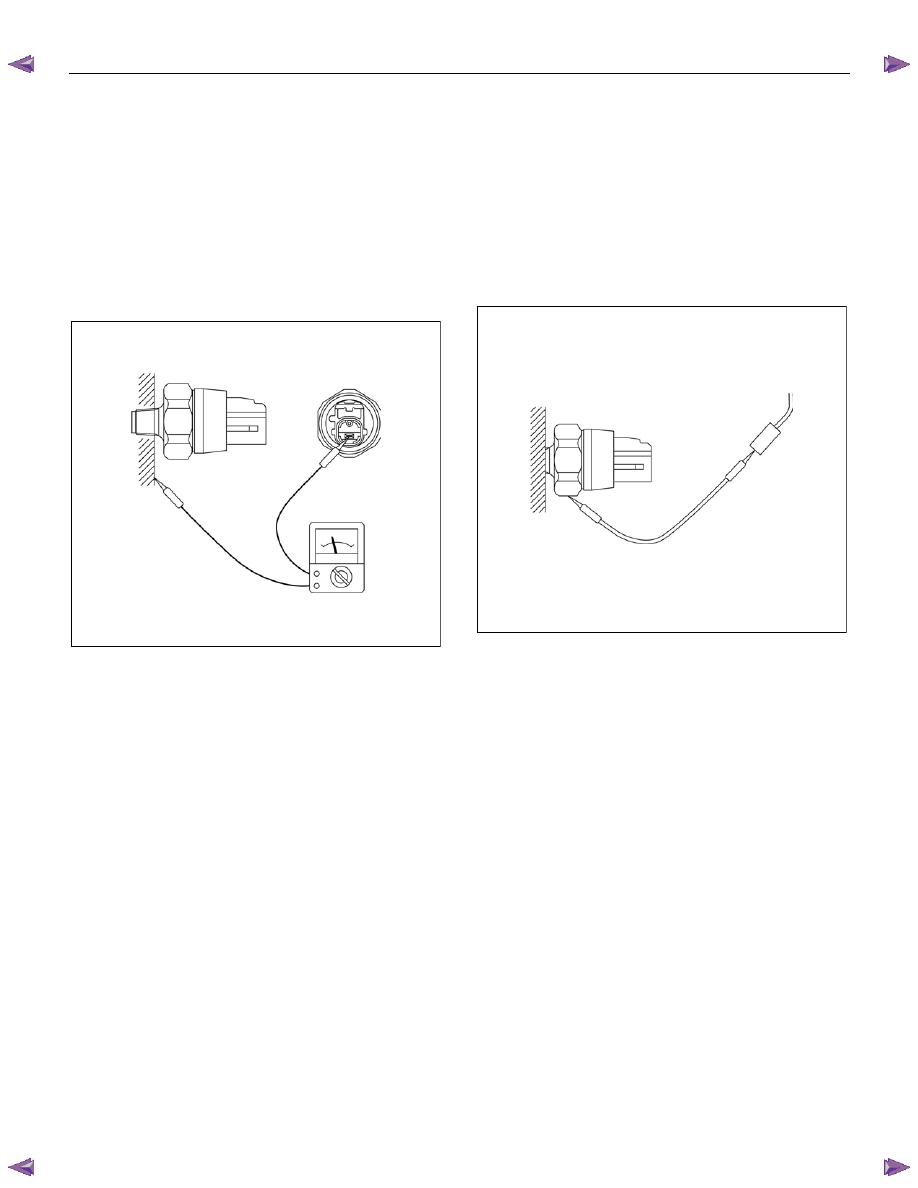
Inspection
Check the continuity between the switch terminal and
the body grounding in a no-load condition.
If there is no connectivity, replace with normal parts.
LNW21HSH003301
Circuit check
1. Turn the starter switch to ON.
2. Disconnect the oil pressure switch connector, and
confirm that the oil pressure-warning lamp lights
when the connector on the harness side is
grounded.
If the warning lamp does not light up, check the
circuit between the meter and the oil pressure
switch, and repair the disconnected locations.
LNW21HSH003401
Installation
1. Install the nipple; oil gallery, oil pressure warning
SW and gasket.
Tightening torque: 25 N
⋅⋅⋅⋅m (2.5 kg⋅⋅⋅⋅m/18 lb ft)
2. Install the Nipple.
Tightening torque: 15 N
⋅⋅⋅⋅m (1.5 kg⋅⋅⋅⋅m/11 lb ft)
3. Install the oil pressure SW.
Tightening torque: 15 N
⋅⋅⋅⋅m (1.5 kg⋅⋅⋅⋅m/11 lb ft)
ENGINE MECHANICAL (4JK1/4JJ1) 6A-163
Air Cleaner Element
Removal
1. Remove the air cleaner cover fixing clip.
2. Remove the air cleaner element assembly.
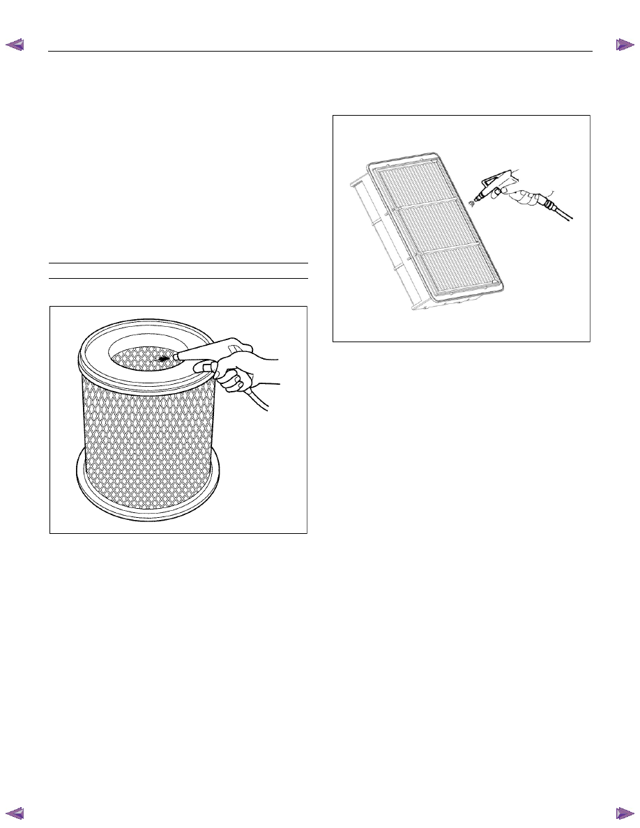
Cleaning
Dry type element
• Rotate the element with your hand while applying
compressed air to the inside of the element. This
will blow the dust free.
Compressed air pressure
kPa (kg/cm
2
/psi)
392
− 490 (4 − 5/57 − 71)
Standard Output
LNW46ASH003201
High Output
LNW71BSH000201
Installation
1. Install the air cleaner element assembly.
2. Install the air cleaner cover.
Нет комментариевНе стесняйтесь поделиться с нами вашим ценным мнением.
Текст