Isuzu KB P190. Manual — part 379
6A-156 ENGINE MECHANICAL (4JK1/4JJ1)
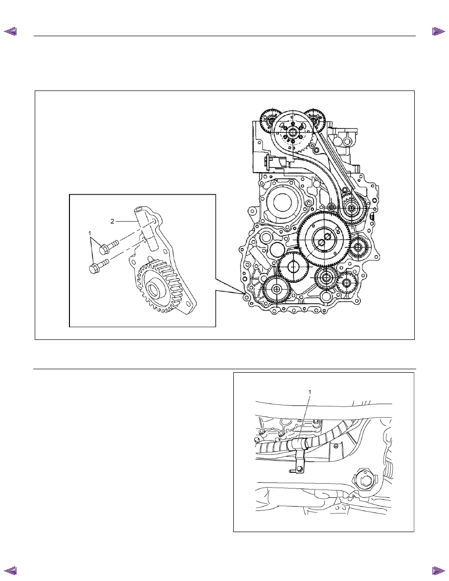
Oil Pump
Components
RTW66AMF000701
Legend
1. Bolt
2. Oil
Pump
Assembly
Removal
1. Drain the engine coolant.
2. Remove the radiator upper hose.
3. Remove the upper fan shroud.
4. Remove the fan and fan clutch.
• Loosen the fan clutch nuts.
• Remove the fan together with the fan clutch.
Take care not to damage the radiator core.
5. Remove the fan drive belt and pulley.
• Loosen the tension adjust bolt on the generator
and A/C.
• Remove the fan drive belt with the fan pulley.
6. Remove the lower fan shroud.
7. Disconnect the power steering pump.
• Disconnect the bracket of the power steering oil
hose clip (1).
LTW56ASH000101
ENGINE MECHANICAL (4JK1/4JJ1) 6A-157
8. Remove the vacuum pump.
• Remove the vacuum pipe bracket and vacuum
pipe.
• Remove the oil pipe (feed side and return side)
of vacuum pump.
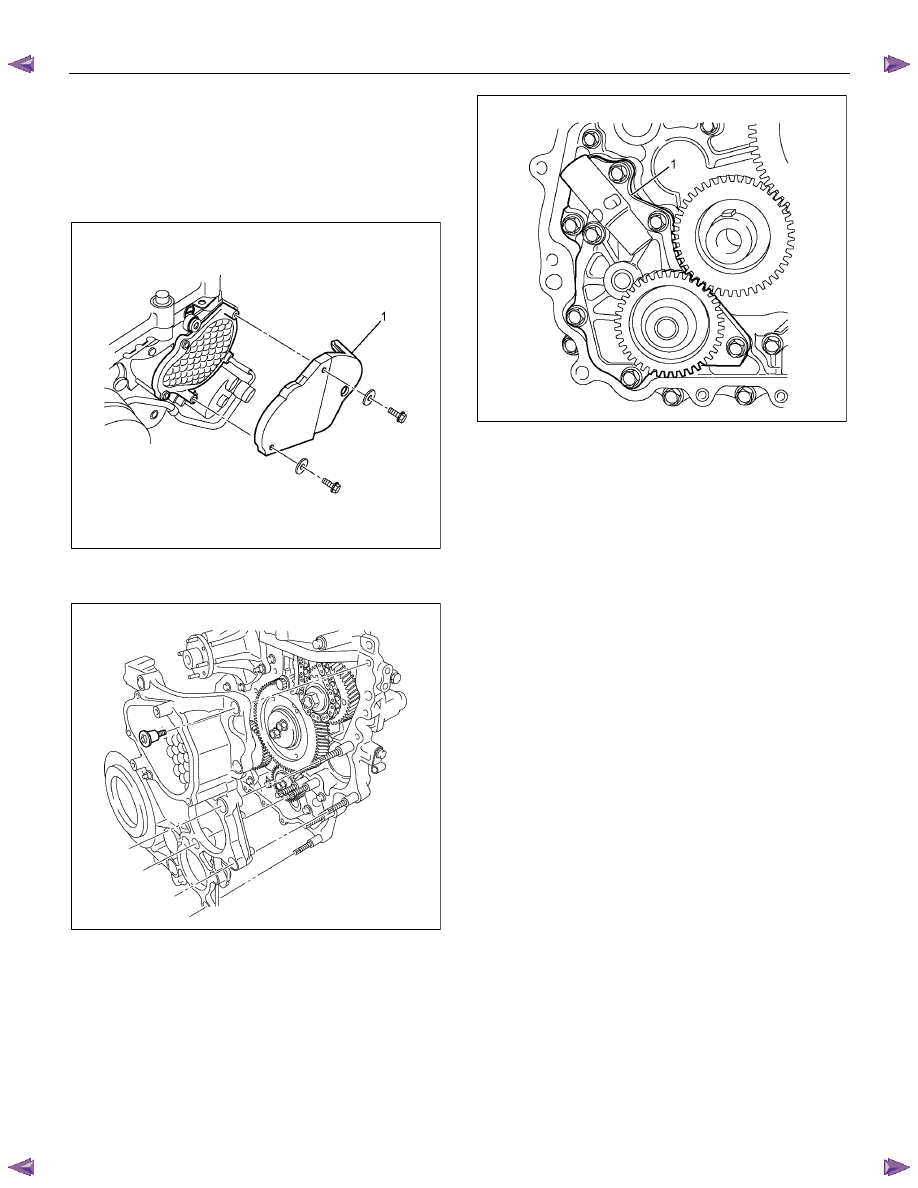
9. Remove the noise cover (1).
RTW56CSH001401
10. Remove the crank pulley.
11. Remove the front cover.
RTW56ASH019701
12. Remove the oil pump (1).
RTW56ASH020001
Disassembly
1. Remove the spring pin.
2. Remove the spring seat.
3. Remove the spring.
4. Remove the valve.
6A-158 ENGINE MECHANICAL (4JK1/4JJ1)
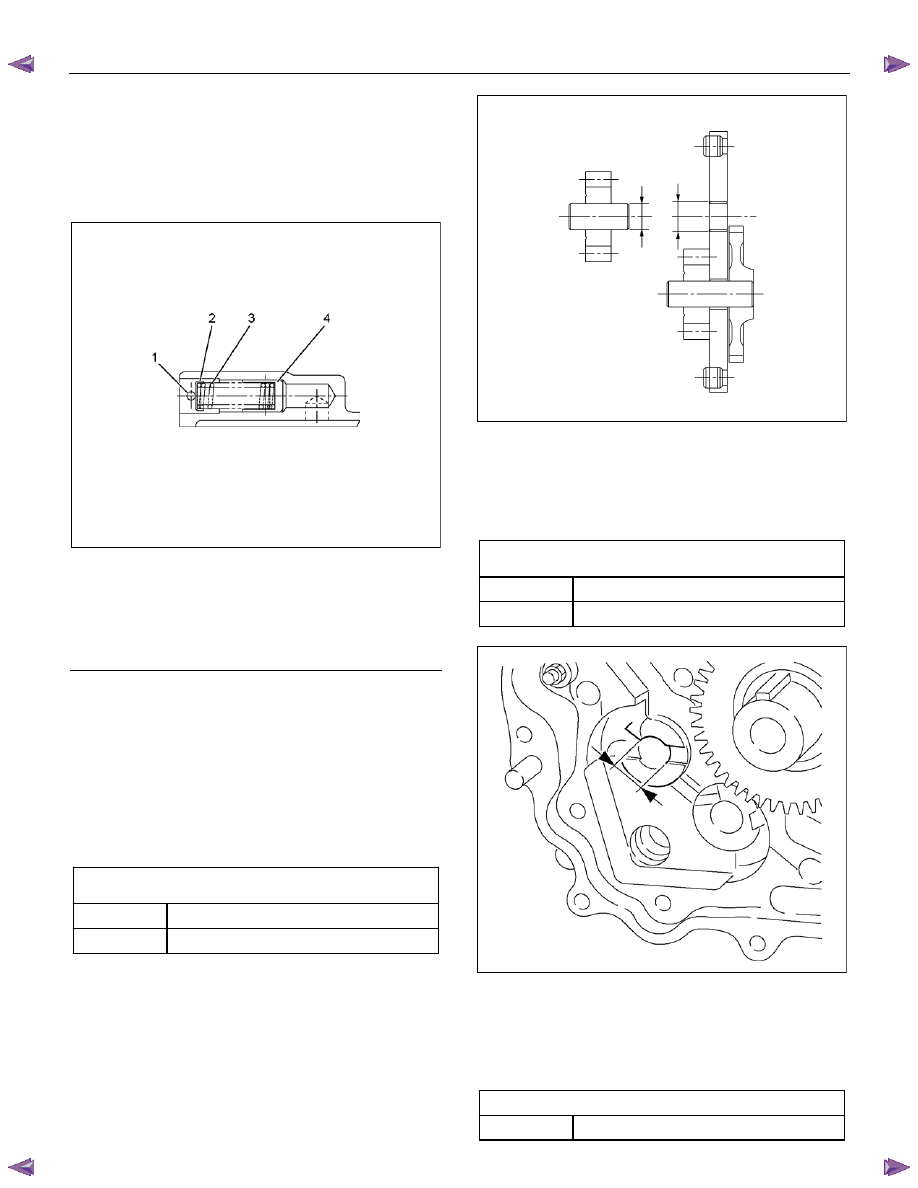
Reassembly
1. Install the valve.
2. Install the spring.
3. Install the spring seat.
4. Install the spring pin.
RTW56ASH015901
Legend
1. Spring
Pin
2. Spring
Seat
3. Spring
4. Valve
Inspection
NOTE:
Think to match direction of ditch of gear when
assembling it.
1. Measure the clearance between the driven
gear/drive gear shaft and the bush.
• Measure the outside diameter of the driven
gear shaft using a micrometer.
Outside diameter of the driven gear shaft/drive
gear shaft
mm (in)
Standard
15.989 - 16.000 (0.62949 - 0.62992)
Limit 15.900
(0.62598)
RTW56ASH025601
• Measure the inside diameter of the bushes of
the cylinder block using the dial gauge.
• If the clearance between the driven gear
shaft/drive gear shaft and bush exceeds the
limit, replace the oil pump assembly.
Clearance between the driven gear shaft/drive gear
shaft and bush
mm (in)
Standard
0.04 - 0.07 (0.0016 - 0.0028)
Limit 0.20
(0.0079)
RTW56ASH014701
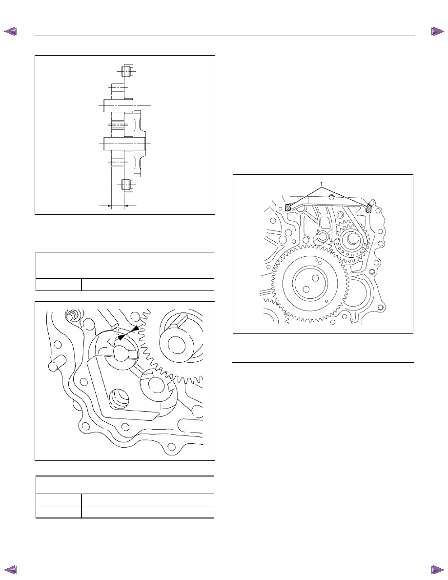
2. Measure the clearance between the gear side
surface and the gear side surface of the oil pump
housing.
• Measure the width size the driven gear/drive
gear.
Width size the driven gear/drive gear
mm (in)
Standard 14.5
(0.5709)
ENGINE MECHANICAL (4JK1/4JJ1) 6A-159
RTW56ASH025501
• Measure the Depth size of the gear case
housing surface and the oil pump housing gear
case side.
Depth size the gear case housing surface and the oil
pump housing gear case side
mm
(in)
Standard
14.500 - 14.527 (0.5709 - 0.5719)
RTW56ASH014801
Clearance between the gear side surface and the
gear side surface of the oil pump housing
mm (in)
Standard
0.063 - 0.027 (0.0025 - 0.0011)
Limit 0.20
(0.0079)
Installation
1. Install the oil pump.
• Apply engine oil to the oil pump attachment
gearbox.
• Tighten the bolts to the specified torque.
Tightening torque: 25 N
⋅⋅⋅⋅m (2.5 kg⋅⋅⋅⋅m / 18 lb ft)
• Installed pump gear should be smooth to
rotate.
2. Install the gear case cover.
• Apply the liquid gasket (Threebond TB-1207B
or equivalent) mount within 5 minutes.
RTW56ASH020101
Legend
1. Apply the liquid gasket in area
Нет комментариевНе стесняйтесь поделиться с нами вашим ценным мнением.
Текст