Isuzu KB P190. Manual — part 150
BRAKE CONTROL SYSTEM 5A-7
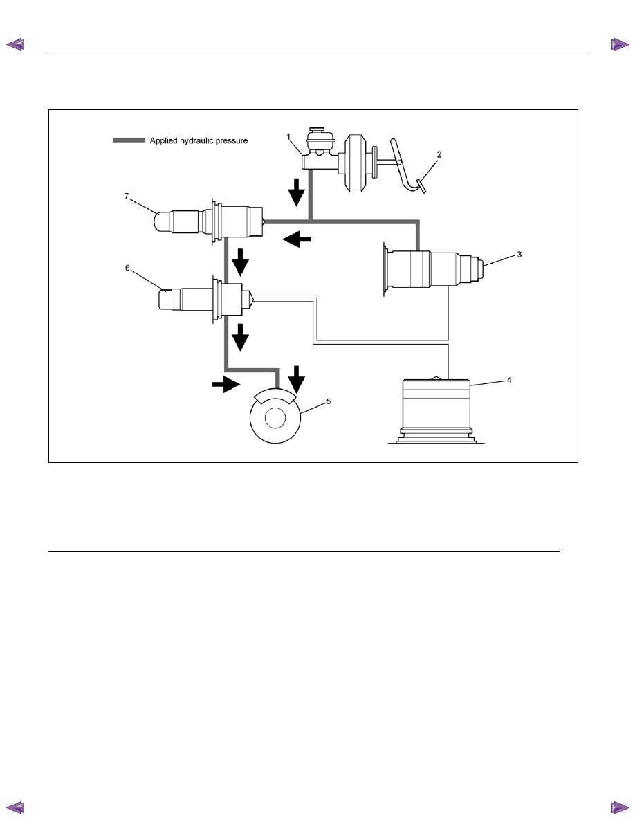
Normal Braking
During normal (non anti-lock) braking, the solenoid
valve has current flow.
Brake fluid travels through the center of the inlet valve
around the outlet valve then to the brake pistons.
RTW75AMF000201
Legend
(1) Master Cylinder
(5) Brake
(2) Brake
Pedal
(6) Outlet Valve
(3) Motor and Pump
(7) Inlet Valve
(4) Accumulator
5A-8 BRAKE CONTROL SYSTEM
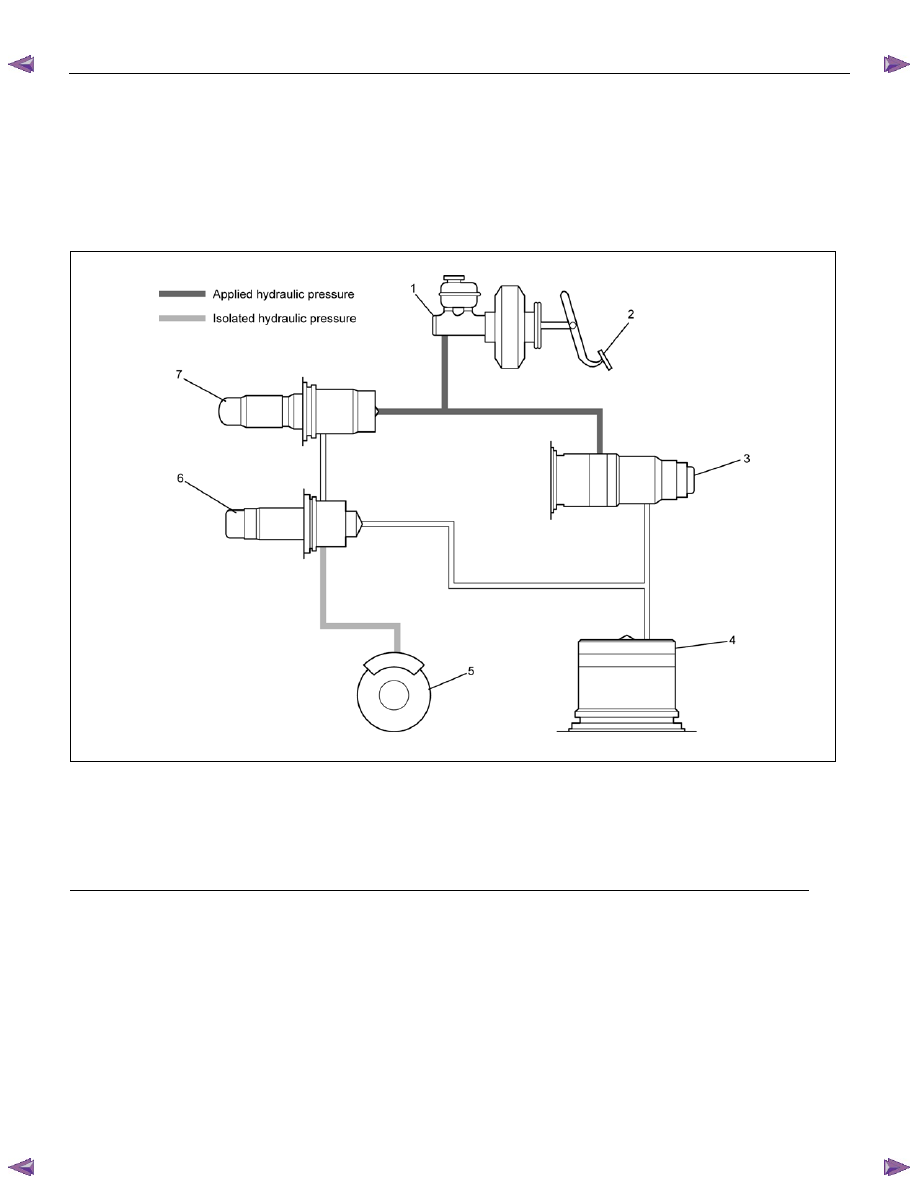
Pressure Isolation (Pressure Maintain)
The electronic-hydraulic control unit is activated when
the brakes are applied.
If the information from the wheel speed sensors
indicates excessive wheel deceleration (imminent
lockup), the first step in the anti-lock sequence is to
isolate the brake pressure being applied by the brake
pedal.
The microprocessor in the Control Unit sends a voltage
to the coil to energize and close the outlet valve. This
prevents any additional fluid pressure applied by the
brake pedal from reaching the wheel. With the outlet
valves closed, unnecessary increase in the brake
pressure is prevented.
RTW75AMF000301
Legend
(1) Master Cylinder
(5) Brake
(2) Brake
Pedal
(6) Outlet Valve
(3) Motor and Pump
(7) Inlet Valve
(4) Accumulator
BRAKE CONTROL SYSTEM 5A-9
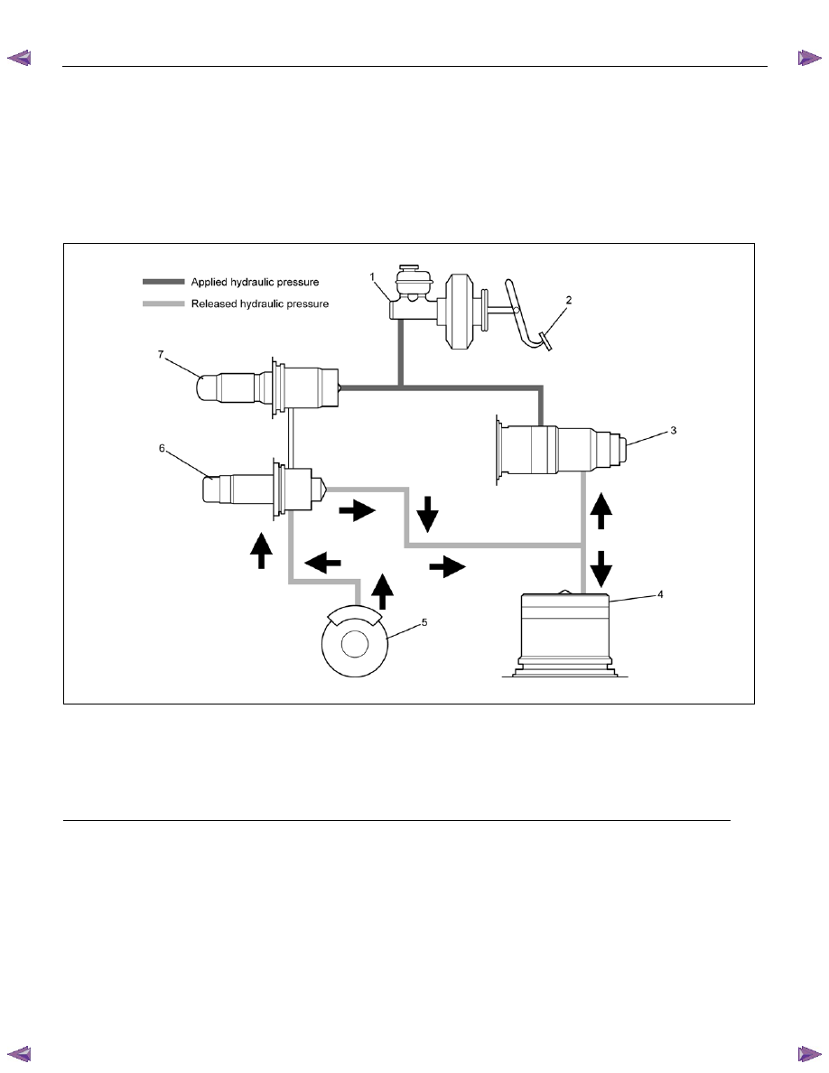
Pressure Reduction
Once the brake pressure is isolated, it must be reduced
to allow the wheels to unlock. This is accomplished by
dumping a portion of the brake fluid pressure into the
accumulator.
The microprocessor activates the normally closed outlet
valve to open, allowing fluid from the wheels to be
dumped into the accumulator. This is done with very
short activation pulses opening and closing the outlet
valve passageway. Brake pressure is reduced at the
wheel and allows the wheel to begin rotating again. The
fluid from the brake piston is stored in the accumulator
against spring pressure and a portion of this fluid also
primes the pump.
The outlet valves are operated independently to control
the deceleration of the wheel.
RTW75AMF000401
Legend
(1) Master Cylinder
(5) Brake
(2) Brake
Pedal
(6) Outlet Valve
(3) Motor and Pump
(7) Inlet Valve
(4) Accumulator
5A-10 BRAKE CONTROL SYSTEM
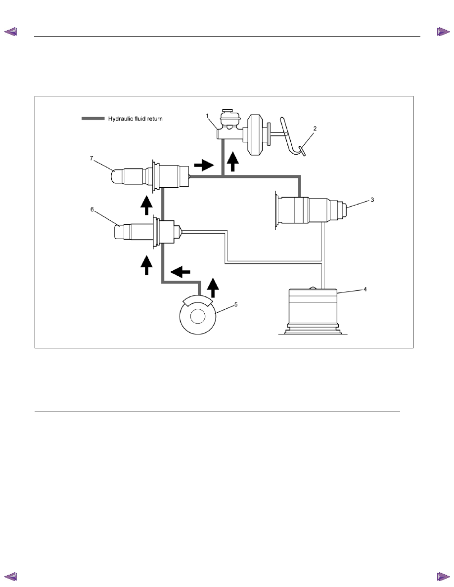
Brake Release
At the end of the anti-lock stop, when the brake pedal is
released, the pump will remain running for a short time
to help drain any fluid from the accumulator. As this fluid
returns into the system, the spring forces the piston
back to its original position.
The inlet valve opens and fluid may return to the master
cylinder. Conventional braking is then resumed.
RTW75AMF000501
Legend
(1) Master Cylinder
(5) Brake
(2) Brake
Pedal
(6) Outlet Valve
(3) Motor and Pump
(7) Inlet Valve
(4) Accumulator
Нет комментариевНе стесняйтесь поделиться с нами вашим ценным мнением.
Текст