Isuzu KB P190. Manual — part 149
BRAKE CONTROL SYSTEM 5A-3
Service Precaution
WARNING: THIS VEHICLE HAS A SUPPLEMENTAL
RESTRAINT SYSTEM (SRS). REFER TO THE SRS
COMPONENT AND WIRING LOCATION VIEW IN
ORDER TO DETERMINE WHETHER YOU ARE
PERFORMING SERVICE ON OR NEAR THE SRS
COMPONENTS OR THE SRS WIRING. WHEN YOU
ARE PERFORMING SERVICE ON OR NEAR THE
SRS COMPONENTS OR THE SRS WIRING, REFER
TO THE SRS SERVICE INFORMATION. FAILURE TO
FOLLOW WARNINGS COULD RESULT IN
POSSIBLE AIR BAG DEPLOYMENT, PERSONAL
INJURY, OR OTHERWISE UNNECESSARY SRS
SYSTEM REPAIRS.
CAUTION: Always use the correct fastener in the
proper location. When you replace a fastener, use
ONLY the exact part number for that application.
ISUZU/GM will call out those fasteners that require
a replacement after removal. ISUZU/GM will also
call out the fasteners that require thread lockers or
thread sealant. UNLESS OTHERWISE SPECIFIED,
do not use supplemental coatings (paints, greases,
or other corrosion inhibitors) on threaded fasteners
or fastener joint interfaces. Generally, such
coatings adversely affect the fastener torque and
the joint clamping force, and may damage the
fastener. When you install fasteners, use the
correct tightening sequence and specifications.
Following these instructions can help you avoid
damage to parts and systems.
5A-4 BRAKE CONTROL SYSTEM
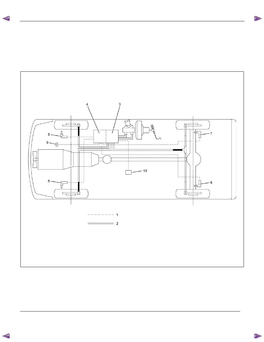
General Description
EHCU has controlled ABS (Anti-lock Brake System) and
EBD (Electronic Brake-force Distribution System). ABS
works on all four wheels. EBD system works on rear 2
wheels. A combination of wheel speed sensor and
Electronic Hydraulic Control Unit (EHCU) can determine
when a wheel is about to stop turning and adjust brake
pressure to maintain best braking.
This system helps the driver maintain greater control of
the vehicle under heavy braking conditions.
Note: The Electronic Hydraulic Control Unit (EHCU)
comprises the Hydraulic Unit (H/U) and Control Unit.
This illustration is based on RHD model
RTW75AMF001101
Legend
(1) Electronic
(6) Front Left Wheel Speed Sensor
(2) Hydraulic
(7) Rear Right Wheel Speed Sensor
(3) Hydraulic Unit (H/U)
(8) Rear Left Wheel Speed Sensor
(4) Control Unit
(9) G sensor (4WD only)
(5) Front Right Wheel Speed Sensor
(10) 2-4WD Control Unit (4WD only)
BRAKE CONTROL SYSTEM 5A-5
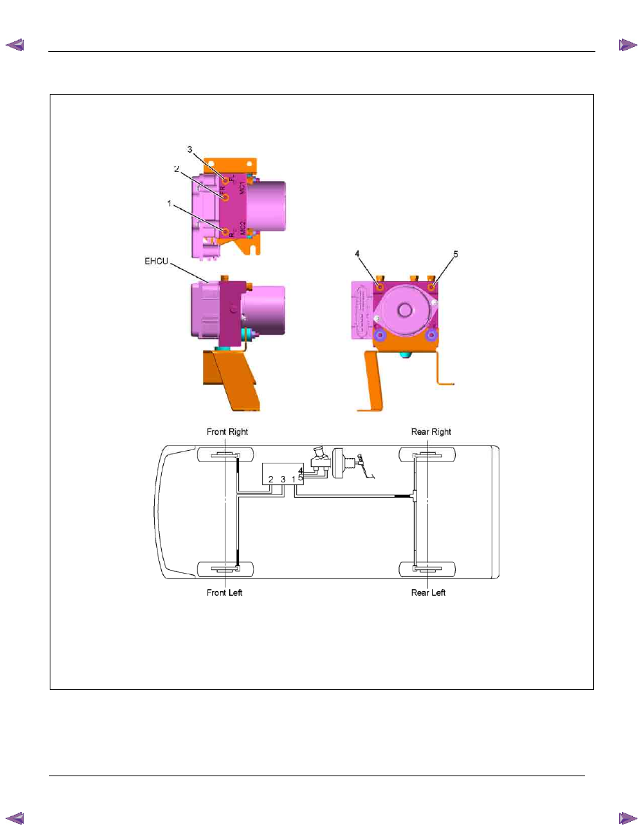
EHCU, Brake Pipe Diagram
This illustration is based on RHD model
RTW75ALF000101
Legend
(1) Rear Brake Port (out)
(4) Rear Brake Port (in)
(2) Front Right Brake Port (out)
(5) Front Brake Port (in)
(3) Front Left Brake Port (out)
5A-6 BRAKE CONTROL SYSTEM
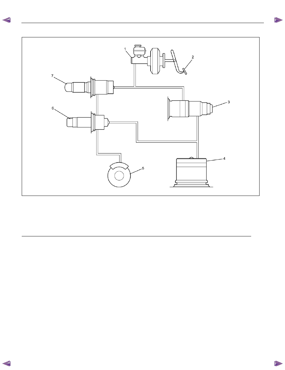
Hydraulic Unit (H/U)
RTW75AMF000101
Legend
(1) Master Cylinder
(5) Brake
(2) Brake
Pedal
(6) Outlet Valve
(3) Motor and Pump
(7) Inlet Valve
(4) Accumulator
Нет комментариевНе стесняйтесь поделиться с нами вашим ценным мнением.
Текст