Isuzu KB P190. Manual — part 644
Engine Mechanical – V6
Page 6A1–97
5
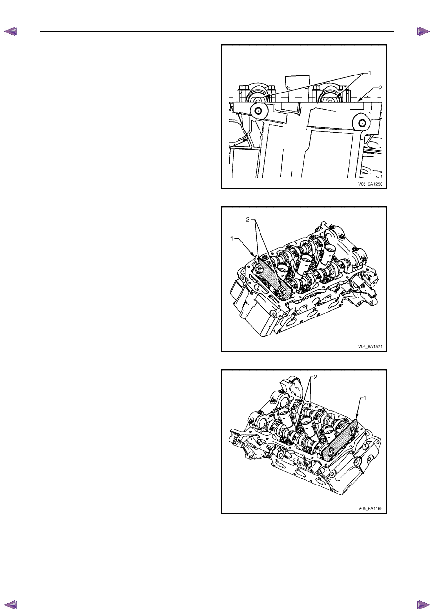
After aligning the crankshaft sprocket timing mark,
check that the camshaft flats (1) at the rear of the
right-hand cylinder head are parallel with the
camshaft cover rail (2).
6
If the camshaft flats are not as shown, rotate the
crankshaft 360
°.
Figure 6A1 – 103
7
Install Tool No. EN 46105-1 (1) onto the rear of the
right-hand cylinder head camshafts (2).
Figure 6A1 – 104
8
Install Tool No. EN 46105-2 (1) onto the rear of the
left-hand cylinder head camshafts (2), and tool No
Figure 6A1 – 105
Engine Mechanical – V6
Page 6A1–98
9
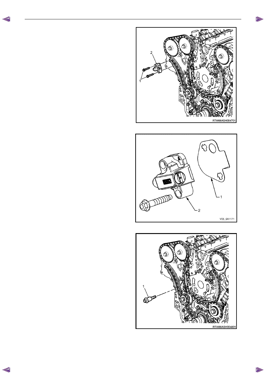
Remove the right-hand secondary timing chain
tensioner bolts (1) and remove the tensioner (2).
N O T E
Take care when removing the tensioner bolts.
The tensioner plunger is subjected to spring
tension and may spring apart during tensioner
removal.
Figure 6A1 – 106
10
Remove the tensioner gasket (1) from the tensioner
(2) and discard the gasket.
11
Inspect the tensioner mounting surface on the right-
hand cylinder head for burrs or any defects that would
affect the sealing of a new tensioner gasket.
Figure 6A1 – 107
12
Remove the right-hand secondary timing chain shoe
bolt (1).
Figure 6A1 – 108
Engine Mechanical – V6
Page 6A1–99
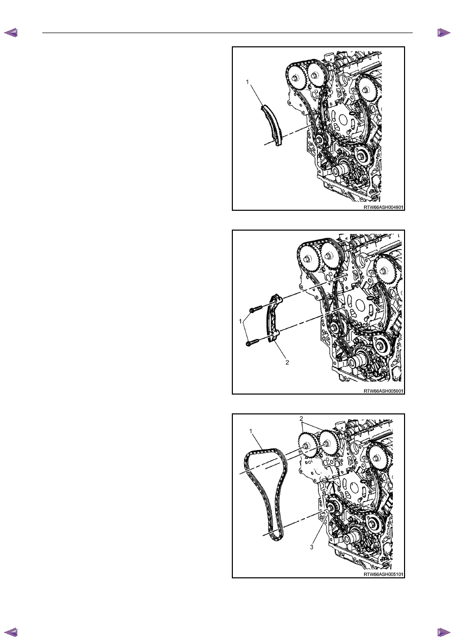
13
Remove the right-hand secondary timing chain shoe
(1).
Figure 6A1 – 109
14
Remove the two right-hand secondary timing chain
guide bolts (1) and remove the guide (2).
Figure 6A1 – 110
15
Remove the right-hand secondary timing chain (1)
from the camshaft position actuators (2) and the
camshaft intermediate driveshaft sprocket (3).
Figure 6A1 – 111

Engine Mechanical – V6
Page 6A1–100
Primary Timing Chain
1
Remove the right-hand secondary timing chain, refer to Right-hand Secondary Timing Chain in this Section.
2
Remove the two primary timing chain tensioner
bolts (1), and remove the tensioner (2).
N O T E
Take care when removing the tensioner bolts.
The tensioner plunger is subjected to spring
tension and may spring apart during tensioner
removal.
Figure 6A1 – 112
3
Remove the gasket (1) from the tensioner (2) and
discard the gasket.
4
Inspect the primary timing chain tensioner mounting
surface on the engine block for burrs or any defects
that would affect the sealing of a new tensioner
gasket.
Figure 6A1 – 113
5
Remove the two primary timing chain upper guide
bolts (1) and remove the guide (2).
Figure 6A1 – 114
Нет комментариевНе стесняйтесь поделиться с нами вашим ценным мнением.
Текст