Isuzu KB P190. Manual — part 645
Engine Mechanical – V6
Page 6A1–101
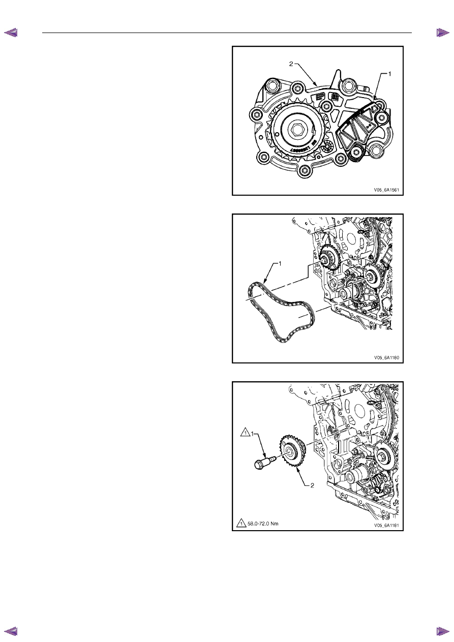
N O T E
Do not remove the primary timing chain lower
guide (1). The primary timing chain lower guide
is not serviced separately. If the primary timing
chain lower guide requires replacement, the oil
pump assembly (2) must be replaced.
Figure 6A1 – 115
6
Remove the primary timing chain (1).
N O T E
For ease of removal, remove the chain from the
crankshaft sprocket, before attempting to
remove from the camshaft intermediate
driveshaft sprockets.
Figure 6A1 – 116
7
If required, remove the right-hand camshaft
intermediate driveshaft sprocket bolt (1) and remove
the sprocket (2).
Figure 6A1 – 117
Engine Mechanical – V6
Page 6A1–102
8
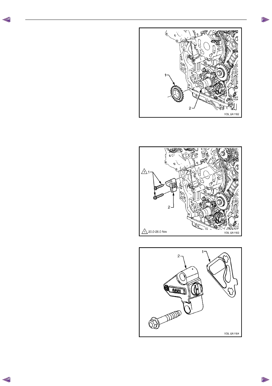
If required, remove the crankshaft sprocket (1) from
the crankshaft (2).
Figure 6A1 – 118
Left-hand Secondary Timing Chain
1
Remove the primary timing chain, refer to Primary Timing Chain in this Section.
2
Remove the two left-hand secondary timing chain
tensioner bolts (1) and remove the tensioner (2).
N O T E
Take care when removing the tensioner bolts.
The tensioner plunger is subjected to spring
tension and may spring apart during tensioner
removal.
Figure 6A1 – 119
3
Remove the gasket (1) from the tensioner (2) and
discard the gasket.
4
Inspect the tensioner mounting surface on the left-
hand cylinder head for burrs or any defects that would
affect the sealing of a new tensioner gasket.
Figure 6A1 – 120
Engine Mechanical – V6
Page 6A1–103
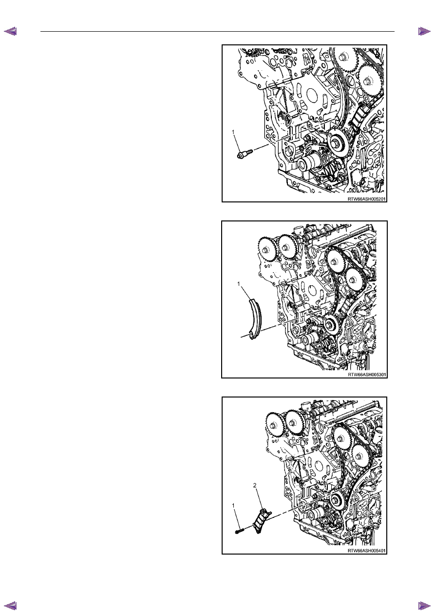
5
Remove the left-hand secondary timing chain shoe
bolt (1).
Figure 6A1 – 121
6
Remove the left-hand secondary timing chain
shoe (1).
Figure 6A1 – 122
7
Remove the left-hand secondary timing chain guide
bolt (1), two places, and remove the guide (2).
Figure 6A1 – 123
Engine Mechanical – V6
Page 6A1–104
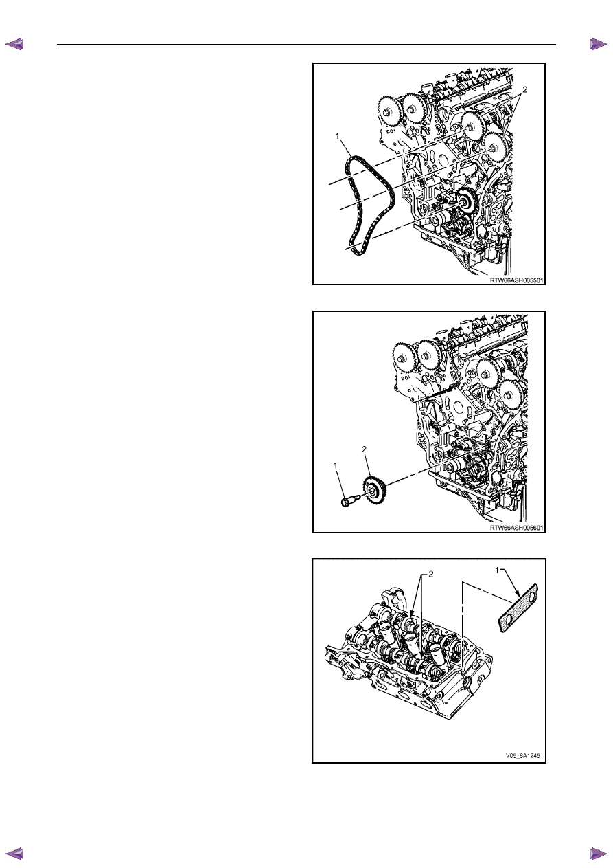
8
Remove the left-hand secondary timing chain (1) from
the camshaft position actuators (2) and the camshaft
intermediate driveshaft sprocket.
Figure 6A1 – 124
9
If required, remove the left-hand camshaft
intermediate driveshaft sprocket bolt (1) and remove
the sprocket (2).
Figure 6A1 – 125
10
Remove Tool No. EN 46105-2 (1) from the left-hand
cylinder head camshafts (2).
Figure 6A1 – 126
Нет комментариевНе стесняйтесь поделиться с нами вашим ценным мнением.
Текст