Isuzu KB P190. Manual — part 622

Engine Mechanical – V6
Page 6A1–9
•
Faulty operation or performance of any systems or components which depend on the proper operation or
performance of the system or component under repair,
•
Damage to fasteners, basic tools or special tools and / or
•
Leakage of coolant, lubricant or other vital fluids.
NOTE defined
A NOTE statement immediately precedes or follows an operating procedure, maintenance practice or condition that
requires highlighting. A NOTE statement also emphasises necessary characteristics of a diagnostic or repair procedure.
A NOTE statement is designed to:
•
Clarify a procedure,
•
Present additional information for accomplishing a procedure,
•
Give insight into the reasons for performing a procedure in the recommended manner, and / or
Present information that gives the technician the benefit of past experience in accomplishing a procedure with greater
ease.
1.2 Engine
Components
Major Component Assemblies
Engine Mechanical – V6
Page 6A1–10
Figure 6A1 – 2
Legend
1 Engine
Assembly
2
Intake Manifold Assembly
3
Camshaft Cover Assembly, Left-hand
4
Camshaft Cover Assembly, Right-hand
5
Engine Front Cover Assembly
6
Oil Pan Assembly
7 Engine
Flywheel
8
Engine Flywheel Bolt
9 Crankshaft
Balancer
10
Crankshaft Balancer Bolt
11
Exhaust Manifold Gasket, Left-hand
12
Exhaust Manifold, Left-hand
13
Exhaust Manifold Heat Shield, Left-hand
14
Exhaust Manifold Heat Shield Bolt, Left-hand
15
Exhaust Manifold Gasket, Right-hand
16
Exhaust Manifold, Right-hand
17
Cylinder Head Exhaust Manifold Bolt
18
Exhaust Manifold Heat Shield, Right-hand
19
Exhaust Manifold Heat Shield Bolt, Right-hand
20
Ignition Coil Assembly
21
Ignition Coil Assembly Bolt
22 Spark
Plug
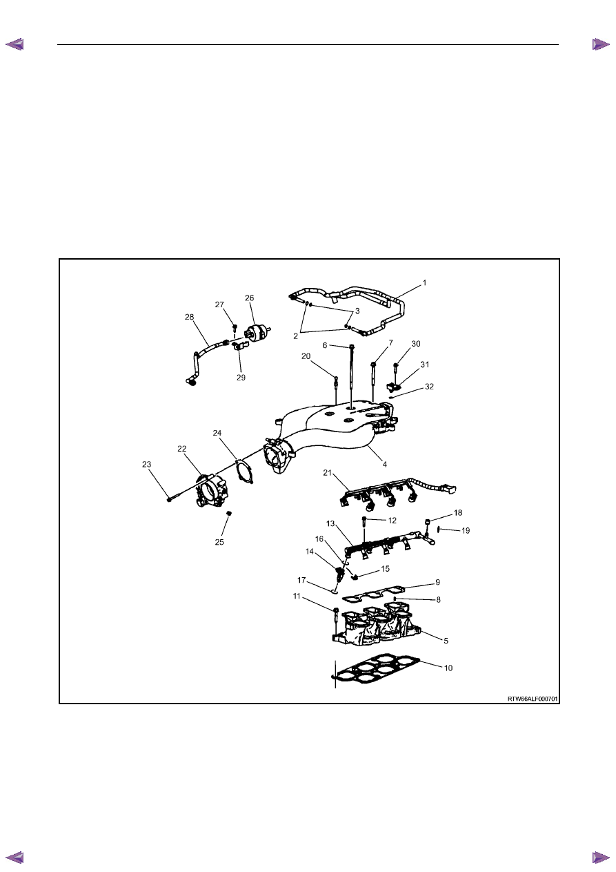
Intake Manifold Assembly
Engine Mechanical – V6
Page 6A1–11
Figure 6A1 – 3
Legend
1 PCV
Hose
2
PCV Hose O-Ring Outer (larger)
3
PCV Hose O-Ring Inner (smaller)
4
Upper Intake Manifold
5
Lower Intake Manifold
6
Upper Intake Manifold Bolt – Long
7
Upper Intake Manifold Bolt – Short
8
Lower Intake Manifold to Upper Intake Manifold Guide Pin
9
Upper Intake Manifold to Lower Intake Manifold Gasket
10
Lower Intake Manifold to Cylinder Head Gasket
11
Lower Intake Manifold Bolt
12
Fuel Rail Bolt
13 Fuel
Rail
14 Fuel
Injector
15
Fuel Injector Retainer
16
Fuel Injector Upper O-ring
17
Fuel Injector Lower O-ring
18
Fuel Pressure Service Valve Cap
19
Fuel Pressure Service Valve
20 Ball
Stud
21
Fuel Injector Wiring Harness
22 Throttle
Body
23
Throttle Body Bolt
24
Throttle Body Gasket
25
Throttle Body Engine Wiring Harness Clip
26
EVAP Purge Solenoid
27
EVAP Purge Solenoid Bolt
28
EVAP Purge Solenoid Tube
29
EVAP Purge Solenoid Bracket
30
BARO Sensor Bolt
31 BARO
Sensor
32
BARO Sensor O-Ring
Engine Mechanical – V6
Page 6A1–12
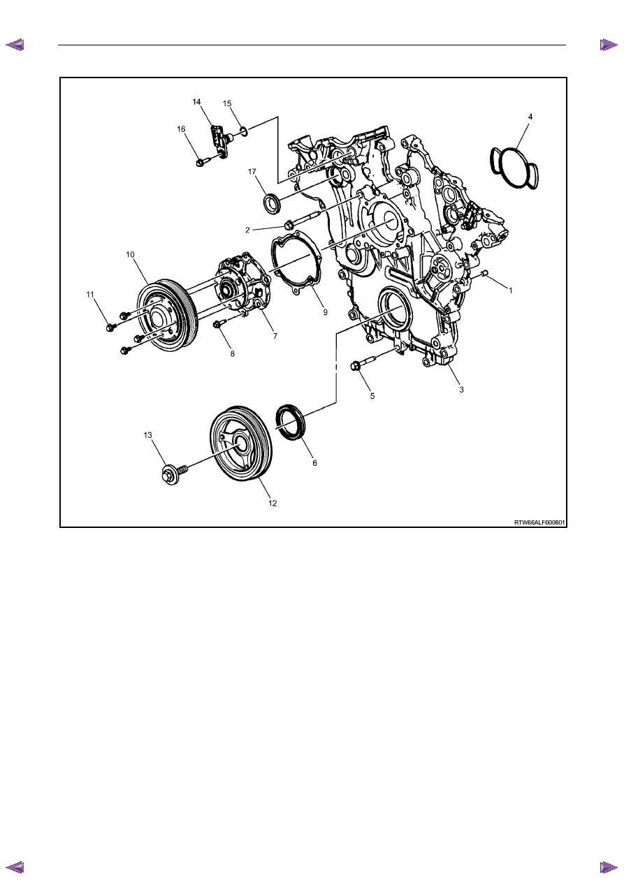
Engine Front Cover
Figure 6A1 – 4
Legend
1
Engine Front Cover Locating Pin
2
Engine Front Cover Bolt, M10
3
Engine Front Cover
4
Engine Front Cover Gasket
5
Engine Front Cover Bolt, M8
6
Engine Front Cover Seal
7
Coolant Pump Assembly
8
Coolant Pump Bolt
9
Coolant Pump Gasket
10
Coolant Pump Pulley
11
Coolant Pump Pulley Bolt
12 Crankshaft
Balancer
13
Crankshaft Balancer Bolt
14
Camshaft Position Sensor
15
Camshaft Position Sensor O-ring
16
Camshaft Position Sensor Bolt
17
Camshaft Position Actuator Solenoid Valve Seal
Нет комментариевНе стесняйтесь поделиться с нами вашим ценным мнением.
Текст