Isuzu KB P190. Manual — part 621
Engine Mechanical – V6
Page 6A1–5
Camshaft Visual Inspection. . . . . . . . . . . . . . . . . . . . . . . . . . . . . . . 150
Camshaft Measurement . . . . . . . . . . . . . . . . . . . . . . . . . . . . . . . . . 151
Reinstall . . . . . . . . . . . . . . . . . . . . . . . . . . . . . . . . . . . . . . . .. 153
Right-hand Side. . . . . . . . . . . . . . . . . . . . . . . . . . . . . . . . . . . .. 153
Left-hand Side . . . . . . . . . . . . . . . . . . . . . . . . . . . . . . . . . . . . 155
3.20
Rocker Arm. . . . . . . . . . . . . . . . . . . . . . . . . . . . . . . . . . . . . . . 158
Remove . . . . . . . . . . . . . . . . . . . . . . . . . . . . . . . . . . . . . . . ... 158
Clean and Inspect . . . . . . . . . . . . . . . . . . . . . . . . . . . . . . . . . . . .. 158
Reinstall . . . . . . . . . . . . . . . . . . . . . . . . . . . . . . . . . . . . . . . .. 159
3.21
Stationary Hydraulic Lash Adjuster . . . . . . . . . . . . . . . . . . . . . . . . . . . . . 160
Remove . . . . . . . . . . . . . . . . . . . . . . . . . . . . . . . . . . . . . . . ... 160
Clean and Inspect . . . . . . . . . . . . . . . . . . . . . . . . . . . . . . . . . . . .. 160
Reinstall . . . . . . . . . . . . . . . . . . . . . . . . . . . . . . . . . . . . . . . .. 161
3.22
Cylinder Head Assembly. . . . . . . . . . . . . . . . . . . . . . . . . . . . . . . . ... 161
Remove . . . . . . . . . . . . . . . . . . . . . . . . . . . . . . . . . . . . . . . ... 161
Right-hand Side (Bank 1) Cylinder Head . . . . . . . . . . . . . . . . . . . . . . . . . ... 161
Left-hand Side (Bank 2) Cylinder Head. . . . . . . . . . . . . . . . . . . . . . . . . . .. 162
Disassemble . . . . . . . . . . . . . . . . . . . . . . . . . . . . . . . . . . . . . ... 163
Clean . . . . . . . . . . . . . . . . . . . . . . . . . . . . . . . . . . . . . . . . ... 166
Inspect . . . . . . . . . . . . . . . . . . . . . . . . . . . . . . . . . . . . . . . . 167
Visual Inspection . . . . . . . . . . . . . . . . . . . . . . . . . . . . . . . . . . . 167
Cylinder Head Measurement. . . . . . . . . . . . . . . . . . . . . . . . . . . . . . .. 167
Valve Spring Inspection and Measurement. . . . . . . . . . . . . . . . . . . . . . . . . 169
Valve and Seat Grinding . . . . . . . . . . . . . . . . . . . . . . . . . . . . . . . . 170
Assemble . . . . . . . . . . . . . . . . . . . . . . . . . . . . . . . . . . . . . . . 174
Reinstall . . . . . . . . . . . . . . . . . . . . . . . . . . . . . . . . . . . . . . . .. 177
Right-hand Side (Bank 1) Cylinder Head . . . . . . . . . . . . . . . . . . . . . . . . . ... 177
Left-hand Side (Bank 2) Cylinder Head. . . . . . . . . . . . . . . . . . . . . . . . . . .. 178
3.23
Engine Mounts and Brackets. . . . . . . . . . . . . . . . . . . . . . . . . . . . . . . 181
Remove. . . . . . . . . . . . . . . . . . . . . . . . . . . . . . . . . . . . . . .. 181
Engine Mount Location . . . . . . . . . . . . . . . . . . . . . . . . . . . . . . . . . . 182
Inspect . . . . . . . . . . . . . . . . . . . . . . . . . . . . . . . . . . . . . . . . 182
Reinstall . . . . . . . . . . . . . . . . . . . . . . . . . . . . . . . . . . . . . . . .. 183
4
Major Service Operations . . . . . . . . . . . . . . . . . . . . . . . . . . . . ..184
4.1
Engine Removal . . . . . . . . . . . . . . . . . . . . . . . . . . . . . . . . . . . . . 184
Remove. . . . . . . . . . . . . . . . . . . . . . . . . . . . . . . . . . . . . . .. 185
Disassemble. . . . . . . . . . . . . . . . . . . . . . . . . . . . . . . . . . . . ... 197
Reassemble . . . . . . . . . . . . . . . . . . . . . . . . . . . . . . . . . . . . ... 198
Reinstall . . . . . . . . . . . . . . . . . . . . . . . . . . . . . . . . . . . . . . . 198
4.2
Oil Pan and Oil Pump Suction Pipe Assembly . . . . . . . . . . . . . . . . . . . . . . . . 198
Remove. . . . . . . . . . . . . . . . . . . . . . . . . . . . . . . . . . . . . . .. 198
Disassemble. . . . . . . . . . . . . . . . . . . . . . . . . . . . . . . . . . . . ... 200
Clean. . . . . . . . . . . . . . . . . . . . . . . . . . . . . . . . . . . . . . . .. 200
Inspect. . . . . . . . . . . . . . . . . . . . . . . . . . . . . . . . . . . . . . . 201
Reassemble . . . . . . . . . . . . . . . . . . . . . . . . . . . . . . . . . . . . ... 201
Reinstall . . . . . . . . . . . . . . . . . . . . . . . . . . . . . . . . . . . . . . . 202
4.3
Flexplate Assembly . . . . . . . . . . . . . . . . . . . . . . . . . . . . . . . . . . ... 203
Remove . . . . . . . . . . . . . . . . . . . . . . . . . . . . . . . . . . . . . . . ... 203
Clean . . . . . . . . . . . . . . . . . . . . . . . . . . . . . . . . . . . . . . . . ... 204
Inspect . . . . . . . . . . . . . . . . . . . . . . . . . . . . . . . . . . . . . . . . 204
Reinstall . . . . . . . . . . . . . . . . . . . . . . . . . . . . . . . . . . . . . . . .. 205
4.4
Crankshaft Rear Seal and Plate Assembly . . . . . . . . . . . . . . . . . . . . . . . . . .. 205
Remove . . . . . . . . . . . . . . . . . . . . . . . . . . . . . . . . . . . . . . . ... 205
Reinstall . . . . . . . . . . . . . . . . . . . . . . . . . . . . . . . . . . . . . . . .. 207
4.5
Pistons, Pins, Rings, Connecting Rods and Big-end Bearings . . . . . . . . . . . . . . . . . . 208
Remove . . . . . . . . . . . . . . . . . . . . . . . . . . . . . . . . . . . . . . . ... 208
Disassemble . . . . . . . . . . . . . . . . . . . . . . . . . . . . . . . . . . . . . ... 211
Clean and Inspect . . . . . . . . . . . . . . . . . . . . . . . . . . . . . . . . . . . .. 212
Engine Mechanical – V6
Page 6A1–6
Piston Cleaning Procedure. . . . . . . . . . . . . . . . . . . . . . . . . . . . . . . . 212
Piston Inspection Procedure . . . . . . . . . . . . . . . . . . . . . . . . . . . . . . .. 213
Piston Measurement . . . . . . . . . . . . . . . . . . . . . . . . . . . . . . . . . .. 213
Piston Ring Measurement . . . . . . . . . . . . . . . . . . . . . . . . . . . . . . . .. 214
Connecting Rod Cleaning Procedure . . . . . . . . . . . . . . . . . . . . . . . . . . . . 215
Connecting Rod Visual Inspection Procedure . . . . . . . . . . . . . . . . . . . . . . . . 215
Connecting Rod Measurement Procedure . . . . . . . . . . . . . . . . . . . . . . . . . . 216
Reassemble . . . . . . . . . . . . . . . . . . . . . . . . . . . . . . . . . . . . . . 217
Piston and Piston Pin . . . . . . . . . . . . . . . . . . . . . . . . . . . . . . . . . . 217
Piston Ring. . . . . . . . . . . . . . . . . . . . . . . . . . . . . . . . . . . . . . 218
Connecting Rod Bearing . . . . . . . . . . . . . . . . . . . . . . . . . . . . . . . . 219
Reinstall . . . . . . . . . . . . . . . . . . . . . . . . . . . . . . . . . . . . . . . .. 220
Piston Connecting Rod and Connecting Rod Bearing Installation. . . . . . . . . . . . . . . . .. 220
Connecting Rod Bearing Clearance Measurement Procedure. . . . . . . . . . . . . . . . . ... 221
Connecting Rod Final Assembly Procedure. . . . . . . . . . . . . . . . . . . . . . . . ... 222
4.6
Crankshaft and Main Bearings . . . . . . . . . . . . . . . . . . . . . . . . . . . . . . . 223
Crankshaft End Play Measurement . . . . . . . . . . . . . . . . . . . . . . . . . . . . .. 223
Remove . . . . . . . . . . . . . . . . . . . . . . . . . . . . . . . . . . . . . . . ... 223
Crankshaft Bearing. . . . . . . . . . . . . . . . . . . . . . . . . . . . . . . . . . . 225
Clean and Inspect . . . . . . . . . . . . . . . . . . . . . . . . . . . . . . . . . . . .. 225
Crankshaft and Main Bearing Cleaning. . . . . . . . . . . . . . . . . . . . . . . . . . .. 225
Crankshaft and Main Bearing Visual Inspection . . . . . . . . . . . . . . . . . . . . . . . . 226
Crankshaft Main Bearing Inspection. . . . . . . . . . . . . . . . . . . . . . . . . . . ... 227
Crankshaft Measurement . . . . . . . . . . . . . . . . . . . . . . . . . . . . . . . ... 228
Reinstall . . . . . . . . . . . . . . . . . . . . . . . . . . . . . . . . . . . . . . . .. 230
Crankshaft Bearing Installation Procedure . . . . . . . . . . . . . . . . . . . . . . . . . . 230
Crankshaft Main Bearing Clearance Measurement. . . . . . . . . . . . . . . . . . . . . . 231
Crankshaft Final Installation Procedure. . . . . . . . . . . . . . . . . . . . . . . . . . .. 233
4.7
Cylinder Block. . . . . . . . . . . . . . . . . . . . . . . . . . . . . . . . . . . . . 234
Disassemble . . . . . . . . . . . . . . . . . . . . . . . . . . . . . . . . . . . . . ... 234
Clean . . . . . . . . . . . . . . . . . . . . . . . . . . . . . . . . . . . . . . . . ... 238
Inspect . . . . . . . . . . . . . . . . . . . . . . . . . . . . . . . . . . . . . . . . 239
Visual Inspection . . . . . . . . . . . . . . . . . . . . . . . . . . . . . . . . . . . 239
Measuring Cylinder Bore Diameter . . . . . . . . . . . . . . . . . . . . . . . . . . . . 239
Measuring Cylinder Bore Taper. . . . . . . . . . . . . . . . . . . . . . . . . . . . . .. 239
Measuring Cylinder Bore Out-of-Round . . . . . . . . . . . . . . . . . . . . . . . . . . . 239
Deck Flatness Inspection . . . . . . . . . . . . . . . . . . . . . . . . . . . . . . . ... 240
Reassemble . . . . . . . . . . . . . . . . . . . . . . . . . . . . . . . . . . . . . . 240
4.8
Thread Repairs. . . . . . . . . . . . . . . . . . . . . . . . . . . . . . . . . . . . ... 244
General Information. . . . . . . . . . . . . . . . . . . . . . . . . . . . . . . . . . ... 244
General Thread Repair. . . . . . . . . . . . . . . . . . . . . . . . . . . . . . . . . ... 246
Main Bearing Cap Bolt Hole Thread Repair . . . . . . . . . . . . . . . . . . . . . . . . . . 251
Cylinder Head Bolt Hole Thread Repair . . . . . . . . . . . . . . . . . . . . . . . . . . ... 257
4.9
Thread Repair Specifications. . . . . . . . . . . . . . . . . . . . . . . . . . . . . . . 263
Left-hand Cylinder Head Camshaft Cover Face . . . . . . . . . . . . . . . . . . . . . . . .. 263
Left-hand Cylinder Head Front Face . . . . . . . . . . . . . . . . . . . . . . . . . . . . 264
Left-hand Cylinder Head Intake Face . . . . . . . . . . . . . . . . . . . . . . . . . . . ... 265
Left-hand Cylinder Head Exhaust Face. . . . . . . . . . . . . . . . . . . . . . . . . . . 266
Left-hand Cylinder Head Rear Face . . . . . . . . . . . . . . . . . . . . . . . . . . . . . 267
Right-hand Cylinder Head Camshaft Cover Face . . . . . . . . . . . . . . . . . . . . . . ... 268
Right-hand Cylinder Head Front Face. . . . . . . . . . . . . . . . . . . . . . . . . . . .. 269
Right-hand Cylinder Head Intake Face. . . . . . . . . . . . . . . . . . . . . . . . . . . . 270
Right-hand Cylinder Head Exhaust Face . . . . . . . . . . . . . . . . . . . . . . . . . . . 271
Right-hand Cylinder Head Rear Face . . . . . . . . . . . . . . . . . . . . . . . . . . . ... 272
Engine Block Front . . . . . . . . . . . . . . . . . . . . . . . . . . . . . . . . . . . 273
Engine Block Left-hand Side . . . . . . . . . . . . . . . . . . . . . . . . . . . . . . . 274
Engine Block Right-hand Side. . . . . . . . . . . . . . . . . . . . . . . . . . . . . . .. 275
Engine Block Rear . . . . . . . . . . . . . . . . . . . . . . . . . . . . . . . . . . . . 276
Engine Block Bottom. . . . . . . . . . . . . . . . . . . . . . . . . . . . . . . . . . . 277
Engine Block Left-hand Deck Face . . . . . . . . . . . . . . . . . . . . . . . . . . . . .. 278
Engine Mechanical – V6
Page 6A1–7
Engine Block Right-hand Deck Face. . . . . . . . . . . . . . . . . . . . . . . . . . . . 279
Engine Front Cover. . . . . . . . . . . . . . . . . . . . . . . . . . . . . . . . . . . 280
Upper Intake Manifold Top . . . . . . . . . . . . . . . . . . . . . . . . . . . . . . . . 281
Upper Intake Manifold Front . . . . . . . . . . . . . . . . . . . . . . . . . . . . . . . . 282
Upper Intake Manifold Rear. . . . . . . . . . . . . . . . . . . . . . . . . . . . . . . ... 283
Lower Intake Manifold Top. . . . . . . . . . . . . . . . . . . . . . . . . . . . . . . . 284
Oil Pan Front . . . . . . . . . . . . . . . . . . . . . . . . . . . . . . . . . . . . . .. 285
Oil Pan Rear. . . . . . . . . . . . . . . . . . . . . . . . . . . . . . . . . . . . . . 286
Oil Pan Bottom . . . . . . . . . . . . . . . . . . . . . . . . . . . . . . . . . . . . ... 287
5
Specifications . . . . . . . . . . . . . . . . . . . . . . . . . . . . . . . . . .288
6
Torque Wrench Specifications. . . . . . . . . . . . . . . . . . . . . . . . . . ..292
7
Special Tools . . . . . . . . . . . . . . . . . . . . . . . . . . . . . . . . . ..294
Engine Mechanical – V6
Page 6A1–8
1 General
Information
The HFV6 engine features a closed vee, deep skirt die cast aluminium cylinder block with cast iron cylinder liners,
internally balanced crankcase, full length water jackets and six bolt main bearing caps.
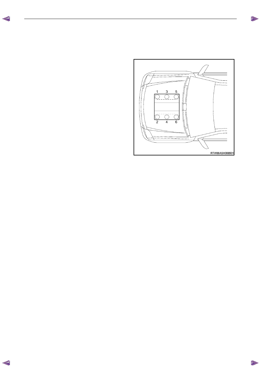
The cylinders are arranged in two banks of three with a 60 degree included angle between the two banks.
The right-hand bank of cylinders consists of number 1-3-5
cylinders and the left-hand bank of cylinders consists of
number 2-4-6.
The engine firing order is 1-2-3-4-5-6.
Each aluminium cylinder head is fitted with hardened valve
seats and four valves per cylinder: two intake and two
exhaust.
The valves are operated by two camshafts (DOHC) per
cylinder bank, one each for intake and exhaust valves.
The crankshaft is manufactured from forged steel. A reluctor
wheel is pressed in place onto the rear of the crankshaft for
the crankshaft position sensor.
The connecting rods are manufactured from powdered
metal and the rod cap is separated during the manufacturing
process using the fractured method. This creates a stronger,
visually seamless rod to cap union.
Figure 6A1 – 1
1.1
WARNING, CAUTION and NOTES
This Section contains various WARNINGS, CAUTIONS and NOTE statements that you must observe carefully to reduce
the risk of death or injury during service, repair procedures or vehicle operation. Incorrect service or repair procedures
may damage the vehicle or cause operational faults. WARNINGS, CAUTION and NOTE statements are not exhaustive.
HOLDEN LTD can not possibly warn of all the potentially hazardous consequences of failure to follow these instructions.
Definition of WARNING, CAUTION and NOTE Statements
Diagnosis and repair procedures in this Section contain both general and specific WARNING, CAUTION and NOTE
statements. HOLDEN LTD is dedicated to the presentation of service information that helps the technician to diagnose
and repair the systems necessary for proper operation of the vehicle. Certain procedures may present a hazard to the
technician if they are not followed in the recommended manner. WARNING, CAUTION and NOTE statements are
designed to help prevent these hazards from occurring, but not all hazards can be foreseen.
WARNING defined
A WARNING statement immediately precedes an operating procedure or maintenance practice which, if not correctly
followed, could result in death or injury. A WARNING statement alerts you to take necessary action or not to take a
prohibited action. If a WARNING statement is ignored, the following consequences may occur:
•
Death or injury to the technician or other personnel working on the vehicle,
•
Death or injury to other people in or near the workplace area, and / or
•
Death or injury to the driver / or passenger(s) of the vehicle or other people, if the vehicle has been improperly
repaired.
CAUTION defined
A CAUTION statement immediately precedes an operating procedure or maintenance practice which, if not correctly
followed, could result in damage to or destruction of equipment, or corruption of data. If a CAUTION statement is ignored,
the following consequences may occur:
•
Damage to the vehicle,
•
Unnecessary vehicle repairs or component replacement,
•
Faulty operation or performance of any system or component being repaired,
•
Damage to any system or components which depend on the proper operation of the system or component being
repaired,
Нет комментариевНе стесняйтесь поделиться с нами вашим ценным мнением.
Текст