Isuzu KB P190. Manual — part 1399

Cruise Control – HFV6
Page 8C–18
Step Action
Yes
No
24 1
Disconnect the PIM connector B – 97.
2
Using a multimeter set to measure voltage, back probe between
the harness connector B – 97 pin 15 and a known ground.
3
With the aid of an assistant, monitor the voltage on the
multimeter and press and release the cruise control switch to
SET–COAST button.
•
With the switch in the rest position, the multimeter should
display 0 V.
•
With the switch pressed, the multimeter should display
battery voltage.
Does the multimeter display as described?
Go to Step 30
Check for short to
ground or open
circuit on circuit.
Repair as required
(refer to Note 1).
Go to Step 32
25 1
Disconnect the PIM connector B – 97.
2
Using a multimeter set to measure voltage, back probe between
the harness connector B – 97 pin 17 and a known ground.
3
With the aid of an assistant, monitor the voltage on the
multimeter and rotate and release the cruise control switch to
CANCEL position.
•
With the switch in the rest position, the multimeter should
display 0 V.
•
With the switch rotated clockwise, the multimeter should
display battery voltage.
Does the multimeter display as described?
Go to Step 30
Check for short to
ground or open
circuit on circuit.
Repair as required
(refer to Note 1).
Go to Step 32
26 1
Disconnect the ECM connector C – 56.
2
Using a multimeter set to measure voltage, back probe between
the harness connector C – 56 pin 10 and ground.
3
With the aid of an assistant, monitor the voltage on the
multimeter and press and release the brake pedal.
•
With the brake pedal in the rest position, the multimeter
should display 0 V
•
With the brake pedal pressed, the multimeter should
display battery voltage
Does the multimeter display as described?
Go to Step 30
Check for a blown
fuse C-18.
Check for short to
ground or open
circuit
Repair as required
(refer to Note 1).
Go to Step 32
27 1
Disconnect the ECM connector C – 56.
2
Using a multimeter set to measure voltage, back probe between
the harness connector C – 56 pin 46 and ground.
3
With the aid of an assistant, monitor the voltage on the
multimeter and press and release the brake pedal.
•
With the brake pedal in the rest position, the multimeter
should display battery voltage
•
With the brake pedal pressed, the multimeter should
display 0 V.
Does the multimeter display as described?
Go to Step 28
Check for a blown
fuse C-10.
Check for short to
ground or open
circuit
Repair as required
(refer to Note 1).
Go to Step 32

Cruise Control – HFV6
Page 8C–19
Step Action
Yes
No
28 1
Disconnect the ECM connector C – 56.
2
Using a multimeter set to measure voltage, back probe between
the harness connector C – 56 pin 53 and ground.
3
With the aid of an assistant, monitor the voltage on the
multimeter and press and release the clutch pedal.
•
With the clutch pedal in the rest position, the multimeter
should display battery voltage
•
With the clutch pedal pressed, the multimeter should
display 0 V
Does the multimeter display as described?
Go to Step 31
Check for a blown
fuse C-4.
Check for short to
ground or open
circuit
Repair as required
(refer to Note 2).
Go to Step 32
29 Check all associated circuits and connectors for the following:
•
Loose or damaged connections
•
Intermittent faults.
Refer to the Wiring Diagrams in this Section and repair as required.
Was the repair completed?
Go to Step 32
—
30 Replace the PIM, refer to 6E1 Powertrain Interface Module – V6.
Was the repair completed?
Go to Step 32
—
31 Replace the ECM module, refer to 6C1-3 Engine Management – V6
Service Operations.
Was the repair completed?
Go to Step 32
—
32 Operate the system in order to verify the repair.
Did you correct the condition?
System OK
Go to Step 1
When all diagnosis and repairs are completed, clear all DTCs and check the system for correct operation.

Cruise Control – HFV6
Page 8C–20
3 Service
Operations
3.1
Cruise Control Main Switch
Remove
To remove the cruise control main switch, refer to 8 B Cruise Control System.
Test
Test the cruise control main switch, using a multimeter set to measure ohms check the continuity.
Figure 8C – 8
Terminal Testing
Cruise Control Main Switch
Switch Terminals
Switch
Position
Indication if Switch
is Serviceable
1 and 2
Switch Illumination
Approx. 22 ohms
4 and 6
Cruise Lamp On Illumination
Approx. 22 ohms
4 and 3
Cruise Switch Released
Open circuit
4 and 3
Cruise Switch Pressed
Short circuit
Reinstall
To reinstall the cruise control main switch, refer to 8 B Cruise Control System.
Cruise Control – HFV6
Page 8C–21
3.2
Cruise Control Switch Assembly
Remove
To remove the cruise control switch assembly, refer to 8 B Cruise Control System.
Test
To test the cruise control switch assembly, use a multimeter to check the continuity.
1
Remove the lower dash trim panel and locate the
cruise control switch assembly wiring harness that
connects a white 13 pin male plug to a connector sub
panel located on the right hand side below of the
steering column.
2
Disconnect the 13 pin male plug B – 59 from its mating
connector socket.
3
Place the turn signal and cruise control switch
assembly into the positions detailed in the following
table, refer to Terminal Testing. Position the contacts
of the multimeter onto the terminals and take the
reading. Compare the multimeter readings with the
values in the table.
4
If the switch assembly fails any part of the test, replace
the cruise control switch assembly with a serviceable
item. To replace the switch assembly, refer to 8 B
Cruise Control System.
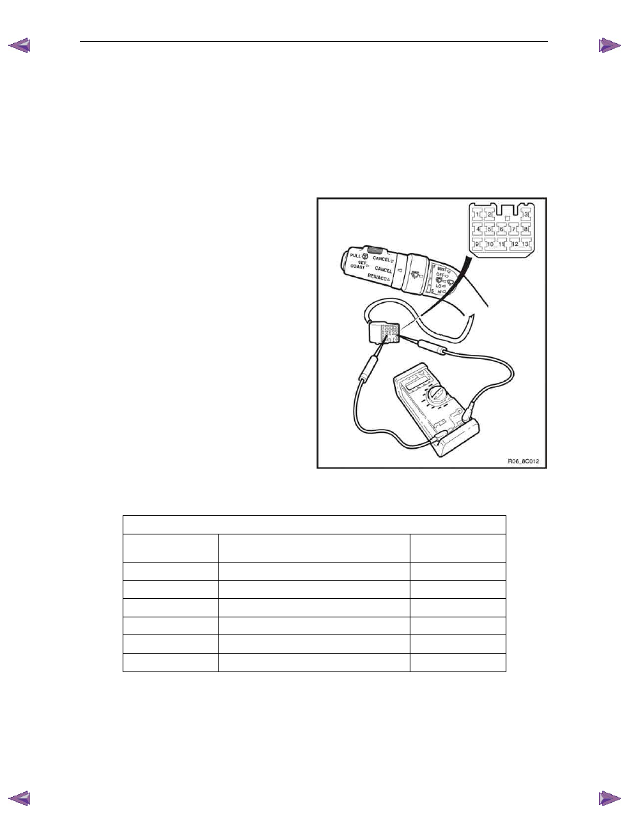
Figure 8C – 9
Terminal Testing
Cruise Control Switch Assembly
Switch Terminals
Switch
Position
Indication if Switch
is Serviceable
11 and 10
CANCEL Applied
Open Circuit
11 and 10
CANCEL Released
Short Circuit
11 and 12
SET–COAST Pressed
Short Circuit
11 and 12
SET–COAST Released
Open Circuit
11 and 9
RES–ACC Applied
Short Circuit
11 and 9
RES–ACC Released
Open Circuit
Reinstall
To reinstall the cruise control switch assembly, refer to 8 B Cruise Control System.
Нет комментариевНе стесняйтесь поделиться с нами вашим ценным мнением.
Текст