Isuzu KB P190. Manual — part 329
6E-282 Engine Control System (4JH1)
Installation Procedure
1. Set the vacuum pressure sensor on the bracket
and tighten a bolt.
2. Connect a harness connector to the vacuum
pressure sensor.
3. Connect the negative battery cable.
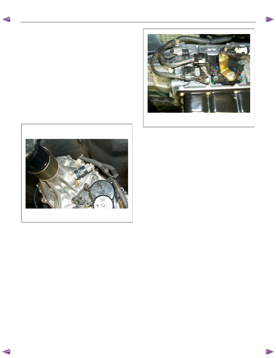
Vehicle Speed Sensor (VSS) Replacement
Removal Procedure
M/T & A/T (4WD)
1. Disconnect the negative battery cable.
2. Disconnect a harness connector from the vehicle
speed sensor (VSS).
3. Remove the VSS from the transmission.
A/T (2WD)
1. Disconnect the negative battery cable.
2. Disconnect a harness connector from the vehicle
speed sensor (VSS).
3. Loosen a bolt and remove the VSS from the
transmission.
Installation Procedure
M/T & A/T (4WD)
1. Install the VSS at the transmission.
2. Connect a harness connector to the VSS.
3. Connect the negative battery cable.
M/T & A/T (4WD)
1. Set the VSS at the transmission and tighten a bolt.
2. Connect a harness connector to the VSS.
3. Connect the negative battery cable.
Engine Control System (4JH1) 6E-283
Description And Operation
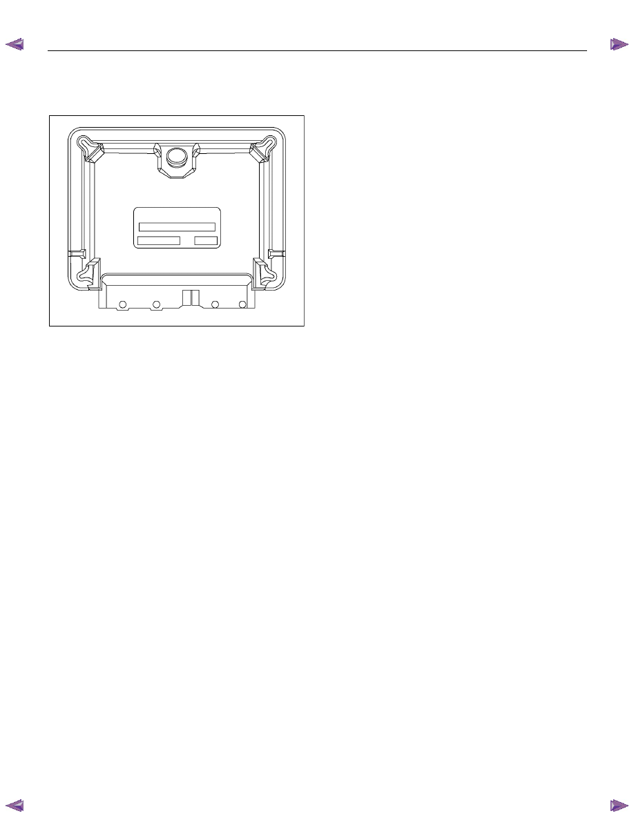
Engine Control Module (ECM) Description
RTW66ESH001201
The engine control module (ECM) is designed to
withstand normal current draws associated with vehicle
operation. Avoid overloading any circuit. When testing
for opens and shorts, do not ground or apply voltage to
any of the ECM circuits unless instructed to do so. In
some cases, these circuits should only be tested using
a digital multi meter (DMM). The ECM should remain
connected to the ECM harness.
The ECM is located on the floor panel. The ECM mainly
controls the following.
• The fuel system control
• The exhaust gas recirculation (EGR) system
control
• The preheating (glow) system control
• The A/C compressor control
• On-board diagnostics for engine control
The ECM constantly observes the information from
various sensor s. The ECM controls the systems that
affect vehicle performance. The ECM performs the
diagnostic function of the system. The ECM can
recognize operational problems, alert the driver through
the malfunction indicator lamp (MIL), and store
diagnostic trouble codes (DTCs). DTCs identify the
system faults to aid the technician in making repairs.
ECM Voltage Description
The ECM supplies a buffered voltage to various
switches and sensor s. The ECM can do this because
resistance in the ECM is so high in value that a test
lamp may not illuminate when connected to the circuit.
An ordinary shop voltmeter may not give an accurate
reading because the voltmeter input impedance is too
low. Use a 10-megaohm input impedance DMM, to
ensure accurate voltage readings. The input and/or
output devices in the ECM include analog-to-digital
converters, signal buffers, counters, and special drivers.
The ECM controls most components with electronic
switches which complete a ground circuit when turned
ON.
Aftermarket Electrical and Vacuum Equipment
Aftermarket or add-on electrical and vacuum equipment
is defined as any equipment which connects to the
vehicle's electrical or vacuum systems that is installed
on a vehicle after the vehicle leaves the factory. No
allowances have been made in the vehicle design for
this type of equipment. No add-on vacuum equipment
should be added to this vehicle. Add-on electrical
equipment must only be connected to the vehicle's
electrical system at the battery power and ground. Add-
on electrical equipment, even when installed to these
guidelines, may still cause the powertrain system to
malfunction. This may also include equipment not
connected to the vehicle electrical system such as
portable telephones and audios. Therefore, the first
step in diagnosing any powertrain fault is to eliminate all
aftermarket electrical equipment from the vehicle. After
this is done, if the fault still exists, the fault may be
diagnosed in the normal manner.
Electrostatic Discharge Damage
Electronic components used in the ECM are often
designed to carry very low voltage. Electronic
components are susceptible to damage caused by
electrostatic discharge. By comparison, as much as
4,000 volts may be needed for a person to feel even the
zap of a static discharge. There are several ways for a
person to become statically charged. The most
common methods of charging are by friction and
induction.
• An example of charging by friction is a person
sliding across a vehicle seat.
6E-284 Engine Control System (4JH1)
Important:
To prevent possible electrostatic discharge damage,
follow these guidelines:
• Do not touch the ECM connector pins or soldered
components on the ECM circuit board.
• Do not open the replacement part package until
the part is ready to be installed.
• Before removing the part from the package,
ground the package to a known good ground on
the vehicle.
• If the part has been handled while sliding across
the seat, while sitting down from a standing
position, or while walking a distance, touch a
known good ground before installing the part.
• Charge by induction occurs when a person with
well insulated shoes stands near a highly charged
object and momentarily touches ground. Charges
of the same polarity are drained off leaving the
person highly charged with opposite polarity.
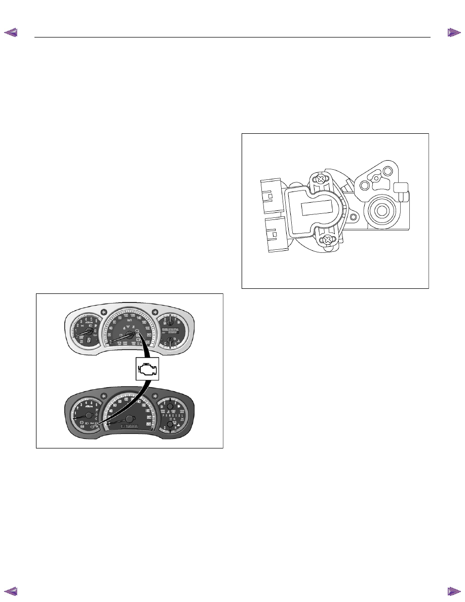
Malfunction Indicator Lamp (MIL) Operation
The malfunction indicator lamp (MIL) is located in the
instrument panel cluster (IPC). The MIL will display the
following symbols when commanded ON:
RTW76ESH004001
The MIL indicates that an emission or performance
related fault has occurred and vehicle service is
required. The following is a list of the modes of
operation for the MIL:
• The MIL illuminates for approximately 2 seconds
when the ignition switch is turned ON, with the
engine OFF. This is a bulb test to ensure the MIL
is able to illuminate.
• The MIL remains illuminated after the engine is
started if the ECM detects a fault. A DTC is stored
any time the ECM illuminates the MIL due to an
emission or performance related fault.
Engine Control Component Description
Accelerator Pedal Position (APP) Sensor & Idle
Switch
RTW66ESH001301
The accelerator pedal position (APP) sensor is mounted
on the throttle assembly. The engine control module
(ECM) uses the APP sensor s to determine the amount
of acceleration or deceleration desired by the person
driving the vehicle via the fuel injection control.
The idle switch is also mounted on the intake throttle
assembly. The idle switch is part of the APP sensor
assembly. The idle switch is a normally closed type
switch. When the accelerator pedal is released, the idle
switch signal to the ECM is low voltage.
Engine Control System (4JH1) 6E-285
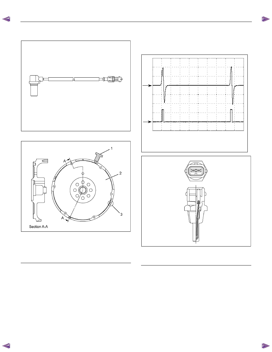
Crankshaft Position (CKP) Sensor
RTW06ESH000101
RTW66ESH001401
Legend
1. Crankshaft Position (CKP) Sensor
2. Flywheel
3. Slit
The crankshaft position (CKP) sensor is located on top
of the flywheel housing. There are 4 slits spaced 90°
on the flywheel circumference. The CKP sensor is a
magnetic coil type sensor , which generates an AC
signal voltage based on the crankshaft rotational speed.
The ECM monitors both the CKP sensor and injection
pump camshaft position (CMP) sensor signals to
ensure they correlate with each other.
The following waveform aids to diagnose when there is
an oscilloscope or equivalent.
Engine Coolant Temperature (ECT) Sensor
- Amplitudes of CKP sensor signal (CH1) increase
as engine speed increases.
- Each waveform cycle shorten as the engine
speed increases.
Terminal: 90 (CH1), 91 (CH2) (+) / GND (-)
Scale: 10V/div 2ms/div
Condition: Approximately 1000RPM
CH1
0V
CH2
0V
RTW66ESH001501
Legend
1. Engine Coolant Temperature (ECT) Sensor
The engine coolant temperature (ECT) sensor is
installed to the thermostat housing. The ECT sensor is
a variable resistor. The ECT sensor measures the
temperature of the engine coolant. The engine control
module (ECM) supplies 5 volts to the ECT signal circuit
and a ground for the ECT low reference circuit. When
the ECT sensor is cold, the sensor resistance is high.
When the engine coolant temperature increases, the
sensor resistance decreases. With high sensor
resistance, the ECM detects a high voltage on the ECT
signal circuit. With lower sensor resistance, the ECM
detects a lower voltage on the ECT signal circuit.
Нет комментариевНе стесняйтесь поделиться с нами вашим ценным мнением.
Текст