Isuzu KB P190. Manual — part 330
6E-286 Engine Control System (4JH1)
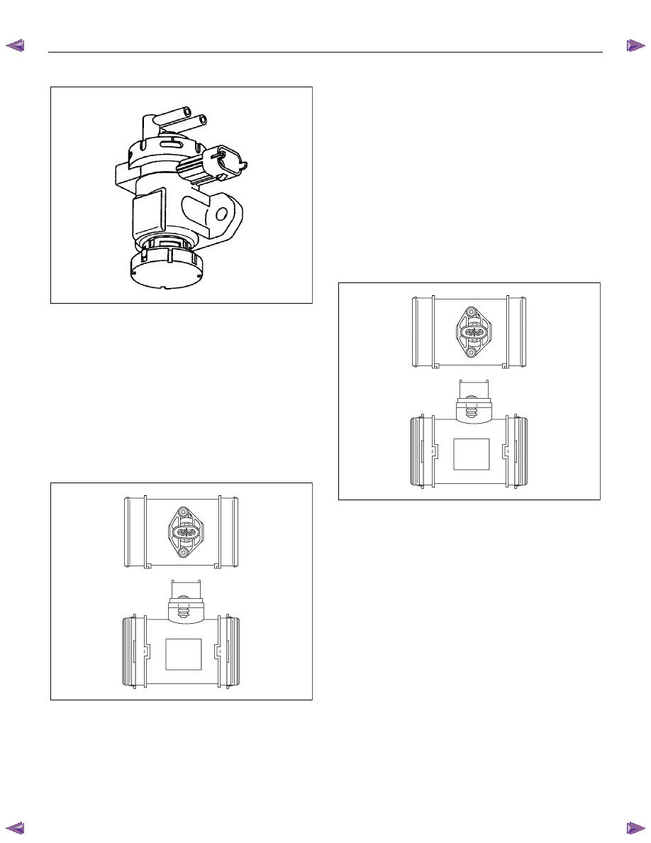
Exhaust Gas Recirculation (EGR) Solenoid Valve
RTW76ESH003601
The engine control module (ECM) controls the exhaust
gas recirculation (EGR) flow amount based on the
engine speed, engine coolant temperature, intake air
temperature, barometric pressure and fuel injection
quantity. The ECM controls the EGR valve by
controlling the EGR solenoid valve. The mass air flow
(MAF) sensor monitors EGR gas flow amount. An
expected MAF amount should be detected while the
engine running.
Intake Air Temperature (IAT) Sensor
RTW66ESH001701
The intake air temperature (IAT) sensor is fitted
between the air cleaner and turbocharger internal to the
mass air flow (MAF) sensor. The IAT sensor is a
variable resistor. The IAT sensor measures the
temperature of the air entering the engine. The engine
control module (ECM) supplies 5 volts to the IAT signal
circuit and a ground for the IAT low reference circuit.
When the IAT sensor is cold, the sensor resistance is
high. When the air temperature increases, the sensor
resistance decreases. With high sensor resistance, the
ECM detects a high voltage on the IAT signal circuit.
With lower sensor resistance, the ECM detects a lower
voltage on the IAT signal circuit.
Mass Air Flow (MAF) Sensor
RTW66ESH001701
The mass air flow (MAF) sensor is an air flow meter that
measures the amount of air that enters the engine. It is
fitted between the air cleaner and turbocharger. A small
quantity of air that enters the engine indicates
deceleration or idle. A large quantity of air that enters
the engine indicates acceleration or a high load
condition. The MAF sensor assembly consists of a MAF
sensor element and an intake air temperature sensor
that are both exposed to the air flow to be measured.
The MAF sensor element measures the partial air mass
through a measurement duct on the sensor housing.
Engine Control System (4JH1) 6E-287
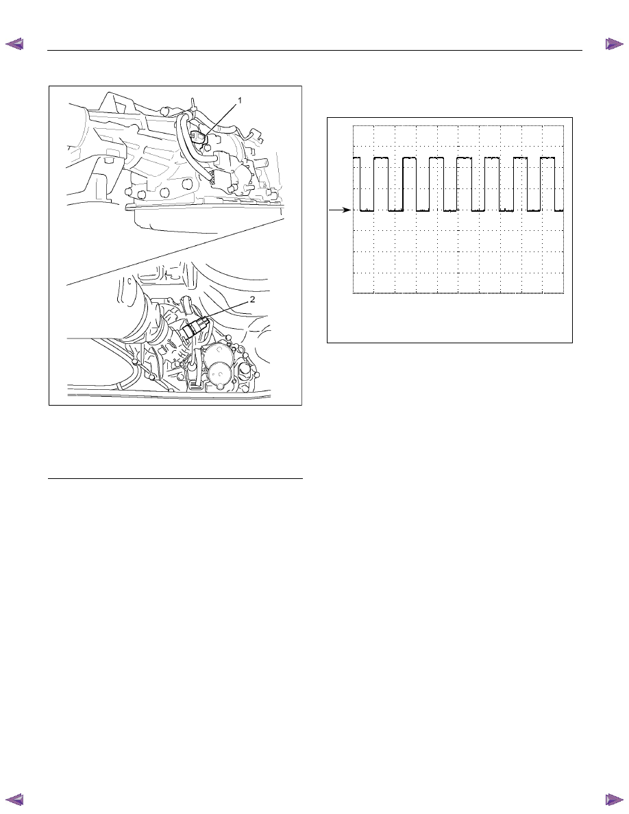
Vehide Speed Sensor (VSS)
RTW56EMH000301
Legend
1. Vehicle Speed Sensor (VSS) 2WD with A/T
2. Vehicle Speed Sensor (VSS) except 2WD with
A/T
The vehicle speed sensor (VSS) is used by the engine
control module (ECM) and speedometer, which
generates a speed signal from the transmission output
shaft. The VSS uses a hall effect element. It interacts
with the magnetic field created by the rotating magnet
and outputs square wave pulse signal. The ECM
calculates the vehicle speed by the VSS.
The following waveform aids to diagnose when there is
an oscilloscope or equivalent.
- VSS waveform cycle shorten as the vehicle
speed increases.
Terminal: 68 (+) / GND (-)
Scale: 5V/div 50ms/div
Condition: Approximately 20km/h (12MPH)
0V

6E-288 Engine Control System (4JH1)
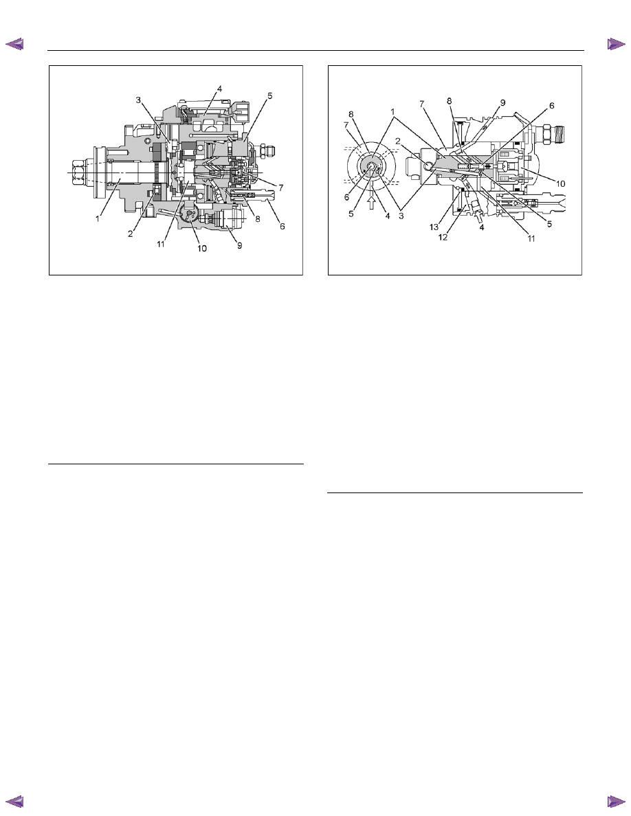
Fuel Injection System Description
RTW66EMF000401
Legend
1. Drive
Shaft
2. Fuel Feed Pump
3. Pump Camshaft Position (CMP) Sensor
4. Fuel Injection Pump Control Unit (PCU)
5. Distributor
Head
6. Constant Pressure Valve (CPV) Holder
7. Fuel Injection Solenoid Valve
8. Constran Pressure Valve (CPV)
9. Timing Control Valve (TCV)
10. Timer
11. Radial Plunger
Bosch VP44 Fuel Injection Pump
Instead of the previous face cam type, the radial
plunger distributor type injection pump utilizes a cam
ring to enable fuel injection at high-pressures, marking it
suitable for small, high-speed direct injection diesel
engines. This pump was developed to provide the most
suitable fuel injection quantity and injection timing to
satisfy the demand for engine reliability, driveability, low
smoke, low noise, high output and low exhaust
emissions.
The engine control module (ECM) calculates the
desired fuel injection quantity and timing using data sent
from various sensor s. These desired data are sent to
the fuel injection pump control unit (PCU) via a
controller area network (CAN) communication bus. The
PCU also receives signals from the internal inputs:
pump camshaft position (CMP) sensor that is located
inside the fuel injection pump to determine the cam ring
rotation angle and the fuel injection pump speed. The
fuel temperature (FT) sensor is internal the PCU. These
values are used to compare the desired values sent
from the ECM then PCU determines the injection timer
piston position and fuel injection quantity, and actuates
timing control valve (TCV) & fuel injection solenoid
valve based on control maps in the PCU.
The timing device changes the optimum injection
timing against various engine conditions. The
pressure of the fuel fed from the feed pump is
adjusted and it acts to the timing plunger by TCV
controlled fuel pressure.
(The TCV is installed to the
fuel injection pump rear side and it is controlled by duty
ratio cycle from the PCU.)
The timing plunger is
connected to the cam ring by a ball pin. Axial
movement of the timing plunger is transferred to the
cam ring in the form of rotational movement.
Engine Control System (4JH1) 6E-289
RTW66ESH001901
Legend
1. Drive
Shaft
2. Feed
Pump
3. Pump Camshaft Position (CMP) Sensor
4. Fuel Injection Pump Control Unit (PCU)
5. Distributor
Head
6. Constant Pressure Valve (CPV) Holder
7. Fuel Injection Solenoid Valve
8. Constant Pressure Valve (CPV)
9. Timing Control Valve (TCV)
10. Timer
11. Radial Plunger
RTW66ESH002001
Legend
1. Rotor
Shaft
2. Radial
Plunger
3. High Pressure Passage
4. Low Pressure Inlet
5. Distribution
Slit
6. Valve
Needle
7. Barrel
8. Annular
Passage
9. Fuel
Return
10. Fuel Injection Solenoid Valve
11. High Pressure Outlet
12. Diaphragm Chamber
13. Accumulator Diaphragm
Нет комментариевНе стесняйтесь поделиться с нами вашим ценным мнением.
Текст