Isuzu KB P190. Manual — part 1064
CONSTRUCTION AND FUNCTION 7A1-17
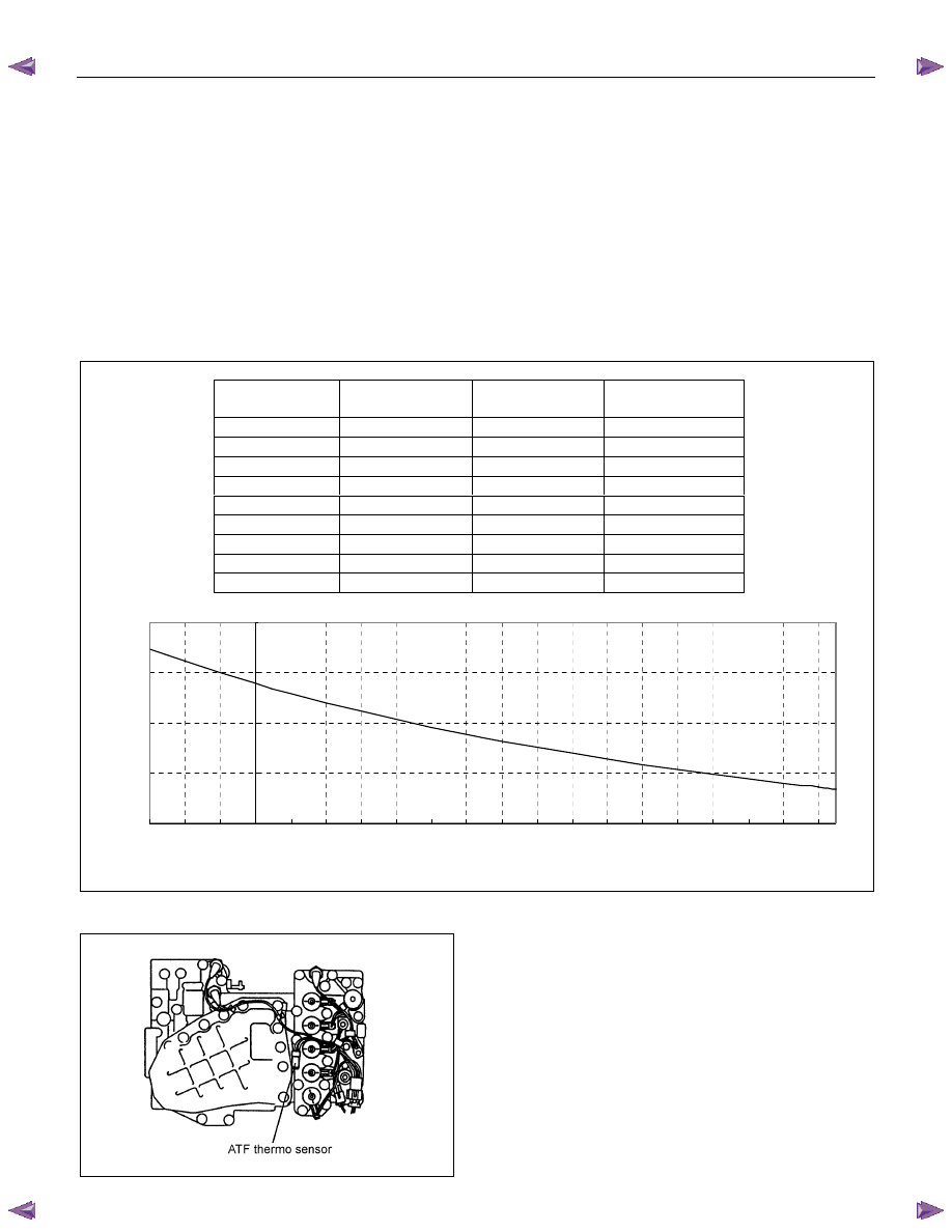
ATF Thermo Sensor
• The ATF thermo sensor detects the ATF temperature in the oil pan and sends a signal to the TCM.
• The ATF thermo sensor is of the thermister type and the resistance value changes according to the ATF
oil temperature.
• When the ATF temperature is cold, the sensor resistance is high. When the ATF temperature increases,
the sensor resistance decreases.
• When the ATF temperature increases to 135°C (275°F), the TCM lights up the ATF temperature warning
lamp in the meter. When the ATF temperature decreases below 125
°C (257°F), the ATF temperature
warning lamp switches off.
• The ATF thermo sensor is installed to the lower control valve body and integrated with the harness
assembly.
10.0
100.0
1,000.0
10,000.0
100,000.0
-30
-20
-10
0
10
20
30
40
50
60
70
80
90
100
110
120
130
140
150
160
ATF Temperature (°C)
R
esistance (
Ω
)
Figure 29. Characteristic of Thermo Sensor
Figure 30. Location of Thermo Sensor
ATF Temperature
(deg. C)
Resistance (Ohm)
(Approximately)
ATF Temperature
(deg. C)
Resistance (Ohm)
(Approximately)
-30 29,614
100
190
-20
16,705
110
149
-10 9,842
120
118
0
6,028
128
98
20
2,500
130
94
40
1,160
135
84
50
819
140
76
60 591
145
68
80 324
150
62
7A1-18 CONSTRUCTION AND FUNCTION
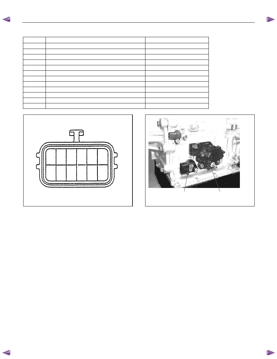
Terminal Assembly
Pin No.
Connected to
Connected TCMPin No.
6
Line Pressure Solenoid
B23
12
Low & Reverse Brake Oil Pressure Switch
B12
5
Low & Reverse Brake Duty Solenoid
B6
11 Ground
Return
B22
4
Lock-up Duty Solenoid
B17
10
High Clutch Duty Solenoid
B8
3
Low Clutch Duty Solenoid
B9
9
2-4 Brake Duty Solenoid
B7
2 Oil
Thermo
Sensor
B4
8
Oil Thermo Sensor Ground
B14
1
High Clutch Oil Pressure Switch
B20
7
2-4 Brake Oil Pressure Switch
B1
1
2
3
4
5
6
8
9
10
11
12
7
Terminal Assembly
Inhibitor Switch
Figure 31. Pin Assignment
Figure 32. Location of Terminal Assembly
CONSTRUCTION AND FUNCTION 7A1-19
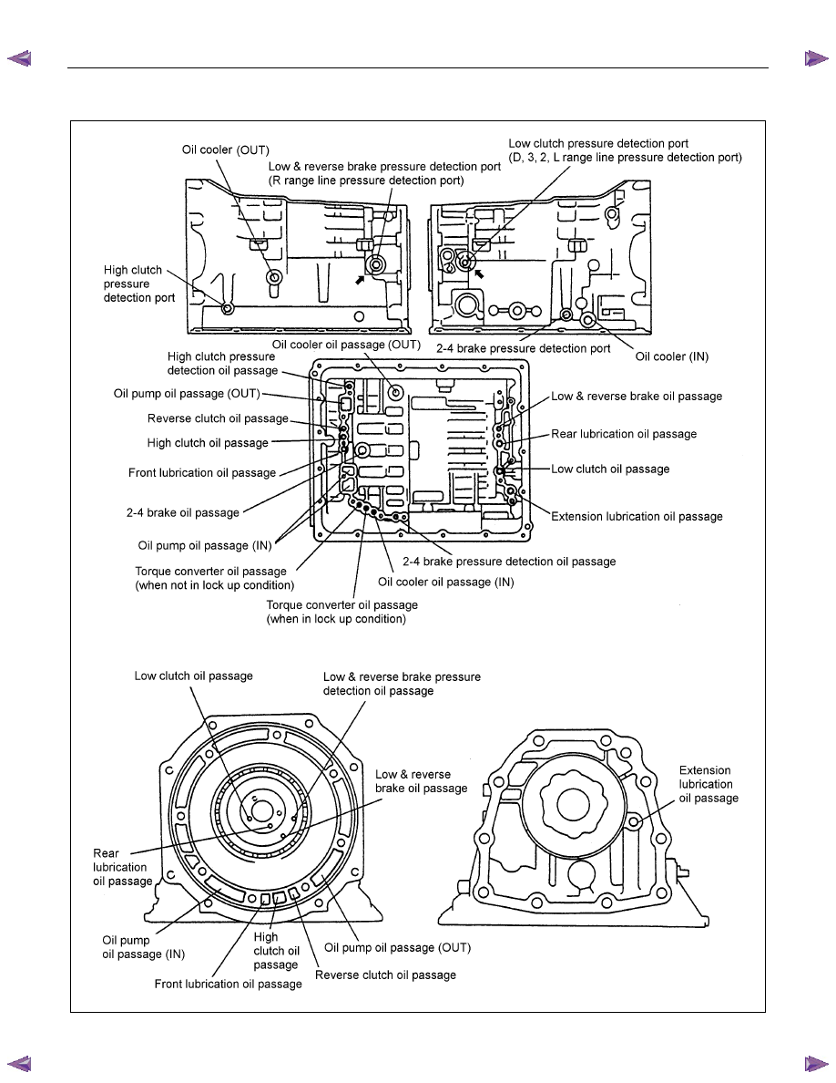
OIL PASSAGE
Figure 33. Oil Passage of Transmission Case
7A1-20 CONSTRUCTION AND FUNCTION
Figure 34. Oil Passage of Oil Pump
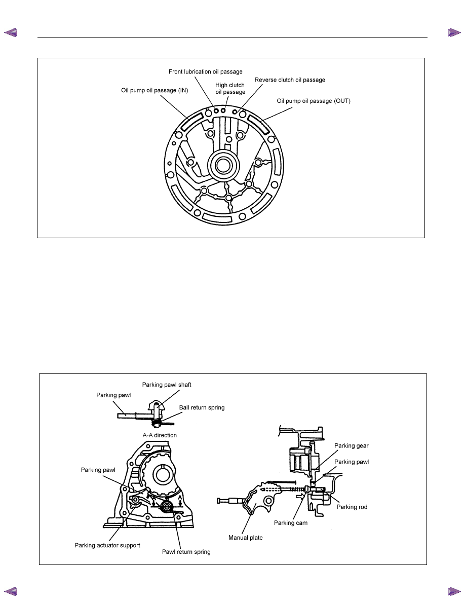
PARKING FUNCTION
• By setting the select lever to the P position, the parking pawl is engaged with the parking gear and fixes
the output shaft.
• By moving the select lever, the manual shaft on the right side of the AT is moved. The manual plate and
parking rod in the AT are interlocked with the manual shaft. When the manual shaft moves, the parking
rod end pushes up the parking pawl.
• The parking pawl is engaged with the parking gear when pushed up, and fixes the output shaft.
• When the clutch is disengaged, it returns to the original position via the force of the return spring, fixed to
the parking pawl.
Figure 35. Parking Function
Нет комментариевНе стесняйтесь поделиться с нами вашим ценным мнением.
Текст