Isuzu KB P190. Manual — part 1062
CONSTRUCTION AND FUNCTION 7A1-9
Figure 7. Lock-up Control (Disengaged)
Figure 8. Lock-up Control (Engaged)
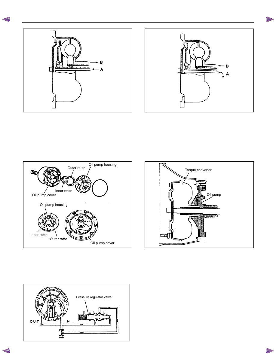
OIL PUMP
• The oil pump generating oil pressure is a small-size trochoid gear type oil pump. It feeds oil to the torque
converter, lubricates the power train mechanism, and feeds the oil pressure to the oil pressure control unit
under pressure.
• The oil pump is located behind the torque converter. Since the inner rotor in the oil pump is fitted with
the drive sleeve of the torque converter, it works using power from the engine.
Figure 9. Construction of Oil Pump
Figure 10. Location of Oil Pump
• When the inner rotor in the oil pump rotates, ATF is sucked in from the oil pan, passed between the inner
rotor, outer rotor and crescent, and then discharged. This discharged pressure is sent to the pressure
regulator valve in the control valve, and adjusted as required for operating the A/T. The flow rate under
pressure increases or decreases in proportion to the number of rotations.
Figure 11. Operation of Oil Pump
7A1-10 CONSTRUCTION AND FUNCTION
INPUT SHAFT
• The input shaft has some oil holes, through which lubricating ATF is supplied to the torque converter, the
bearings, etc.
• The input shaft is fitted to the turbine runner in the torque converter, the reverse & high clutch drum and
the rear sun gear by means of the spline. Therefore, the engine driving force received by the torque
converter is transmitted to the reverse & high clutch drum and rear sun gear.
OUTPUT SHAFT
• The output shaft has some oil holes, through which the lubricating ATF is supplied to the bearings, the
planetary gear unit, etc.
• The output shaft transmits the engine driving force from the planetary gear to the propeller shaft.
• The front internal gear is fitted with the rear carrier assembly by spline. The parking gear is also fitted by
spline. By fixing this gear mechanically, the output shaft is fixed as required when parking the vehicle.
GEAR SHIFTING MECHANISM
• The JR405E consists of two sets of planetary gears, three multiple plate clutches, two multiple plate
brakes and a one-way clutch. They are activated in different combinations in any of four forward and one
reverse gear positions.
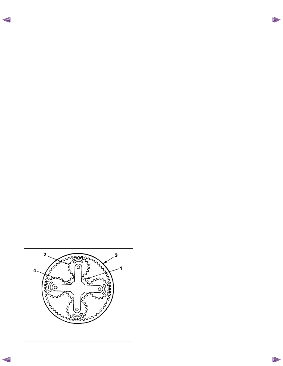
Principle of gear shifting (Figure 12)
• Planetary gears have the advantage of a compact configuration because of the way they are constructed
with a single central shaft.
• Also, unlike the manual transmission gears that require changing of the gear mesh, the gear ratio of the
planetary gears can be changed more easily by locking, releasing or rotating only some of their parts.
• A planetary gear is made up of a sun gear (1) at its center, and pinion gears (2) each of which rotates
about its own center and around the sun gear, as shown. They are all contained within the internal gear
(3).
• Also, since the pinion gears are further supported by the planetary carrier (4), they rotate as a unit in the
same direction, and at the same rate.
• As shown below, each planetary gear is constructed of three elements; a sun gear, pinion gears, an
internal gear and a planetary carrier. Gear shifting is achieved by conditioning two of the three elements,
namely the sun gear, the internal gear and planetary carrier.
• The planetary gears are locked by the clutch, brake and one-way clutch according to the gear shifting.
1. Sun Gear
2. Pinion Gear
3. Internal Gear
4. Planetary Carrier
Figure 12. Planetary Gear
CONSTRUCTION AND FUNCTION 7A1-11
• The JR405E consists of two sets of planetary gears, which are called front planetary gear and rear
planetary gear.
• The sun gear of the front planetary gear is fixed to the drive plates of 2-4 brake and reverse clutch.
• The planetary carrier of the front planetary gear is fixed to the drum of the low clutch, the drive plates of
the low & reverse brake, and the hub of the high clutch.
• The internal gear of the front planetary gear, and the planetary carrier of the rear planetary gear, are
connected as one and fixed to the output shaft.
• The sun gear of the rear planetary gear is fixed to the input shaft.
• The internal gear of the rear planetary gear is fixed to the hub of the low clutch.
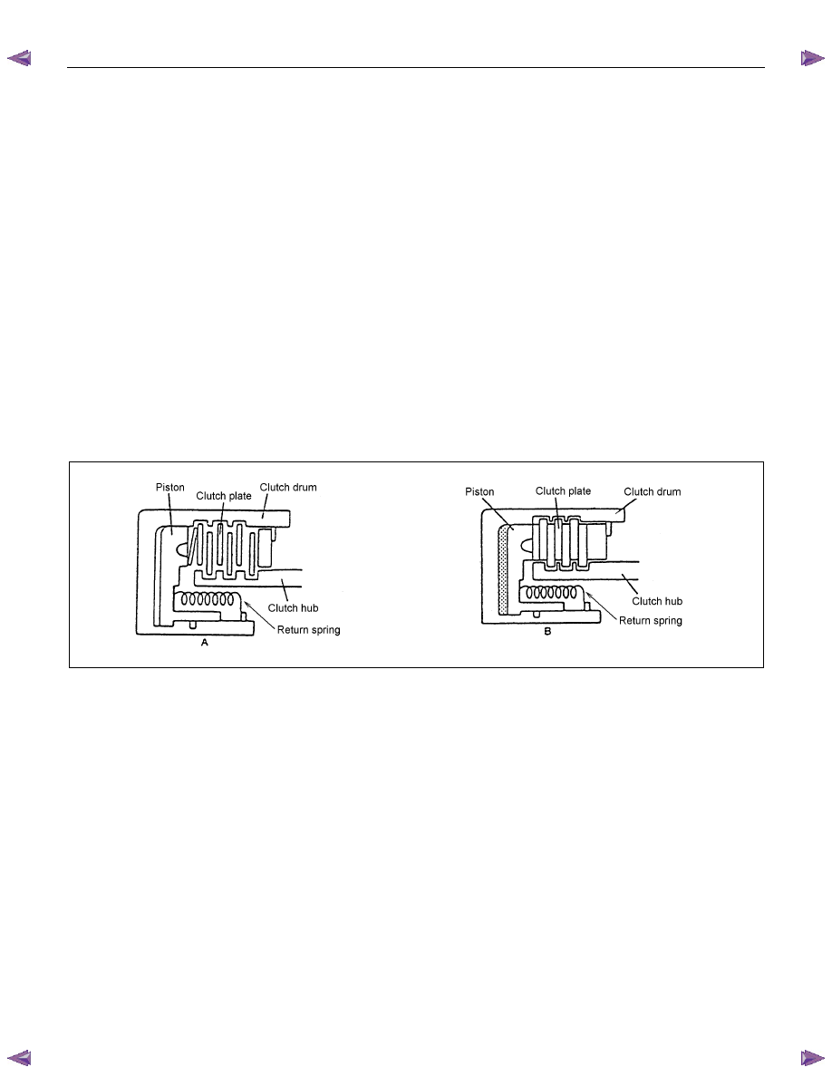
Clutch and Brake
• Basic structure of the clutch and brake is shown in the figures below.
• In the figure A, the clutch plates (drive plate and driven plate) are released so that they slip against each
other, transmitting no power.
• Figure B shows the condition where the oil pressure is acting on the piston. The clutch plates are fitted
to each other under pressure, transmitting the rotations of the clutch drum to the clutch hub.
• When the oil pressure is removed from the piston, the clutch returns to the condition in figure A via the
return spring.
Figure 13. Basic Construction of Clutch and Brake
Low Clutch, High Clutch and Reverse Clutch (Multi-Plate Clutch)
• The multi-plate clutch is composed of drive plates and driven plates. By applying the oil pressure onto
the end surface of the plates, the clutch is engaged. The oil pressure is adjusted with the control valve
according to the signal from the TCM.
• All clutches use dish plates to prevent uncontrolled operation of the clutches when engaged, causing a
shock.
• For the reverse clutch, a piston check ball is used to release the oil pressure. This prevents clutch drag
caused by oil pressure generated by residual ATF due to the centrifugal force while the clutch is racing
(under no oil pressure).
• For the low clutch and high clutch, a centrifugal balance chamber full of ATF is provided to offset the
excessive oil pressure. This prevents clutch drag caused by oil pressure generated by residual ATF due
to the centrifugal force while the clutch is racing (under no oil pressure).
• The solenoid in the control valve is driven based on the shift signal from TCM, it moves the shift valve,
thereby engaging the drive plate and driven plate through the piston of each clutch.
• As a result, elements of the planetary gear unit are combined.
• When the oil pressure is removed, the piston returns to the original position via the force of the return
spring.

7A1-12 CONSTRUCTION AND FUNCTION
Figure 14. Basic Construction of Low Clutch
and High Clutch
Figure 15. Basic Construction of Reverse Clutch
Figure 16. Construction of Low Clutch
Figure 17. Construction of High Clutch
Figure 18. Construction of Reverse Clutch
Нет комментариевНе стесняйтесь поделиться с нами вашим ценным мнением.
Текст