Isuzu KB P190. Manual — part 141
4C1-60 FRONT WHEEL DRIVE
RTW74CSH00030
1
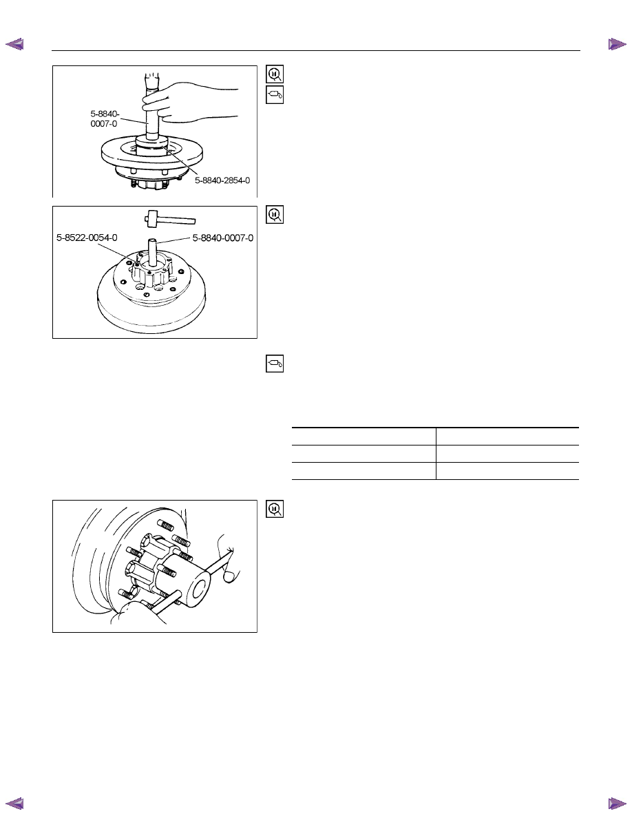
17. Oil Seal
Installer : 5-8840-2854-0
Grip :
5-8840-0007-0
Apply grease (Besco L-2 or equivalent) to the lip portion.
Discard the used oil seal and install a new one.
RTW44CSH00020
1
18. Outer bearing
Outer race ; outer bearing
Install the outer race by driving it into the hub.
Installer : 5-8522-0054-0
Grip :
5-8840-0007-0
19. Hub and Disc Assembly
(
1) Apply grease in the hub.
(2) Apply grease (Besco L-2 or equivalent) to the outer and
inner bearing.
g(oz)
Hub
35 (
1.23)
Outer bearing
10 (0.35)
Inner bearing
15 (0.53)
20. Hub Nut
(
1) Turn the place where there is a chamfer in the tapped hole
to the outer side, and attach the nut.
Wrench : 5-8840-2
117-0
FRONT WHEEL DRIVE 4C1-61
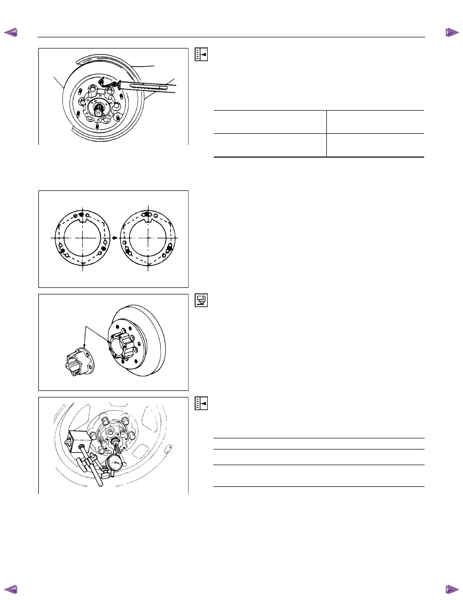
Preload Adjustment
Tighten the hub nut at 29 N
⋅m (3.0 kgf⋅m / 22 lb⋅ft), then loosen
the nut to the full.
Tighten the hub nut at the value given below, using a spring
scale on the wheel pin.
Bearing Preload
N (kgf/lb)
New bearing and New oil seal
22 - 27
(2.2 - 2.8 / 4.9 - 6.2)
Used bearing and New oil seal
14 - 20
(
1.4 - 2.0 / 3.1 - 4.5)
If the measured bearing preload is outside the specifications,
adjust it by loosening or tightening the bearing nut.
21. Lock Washer
Turn the side with larger diameter of the tapered bore to the
vehicle outer side, and attach the washer.
If the bolt holes in the lock plate are not aligned with the
corresponding holes in the nut, reverse the lock plate.
If the bolt holes are still out of alignment, turn in the nut just
enough to obtain alignment,. Screw is to be fastened tightly so
its head may come lower than the surface of the washer.
22. Body Assembly
Apply adhesive (Loctite 5
15 or equivalent) to the both joining
faces.
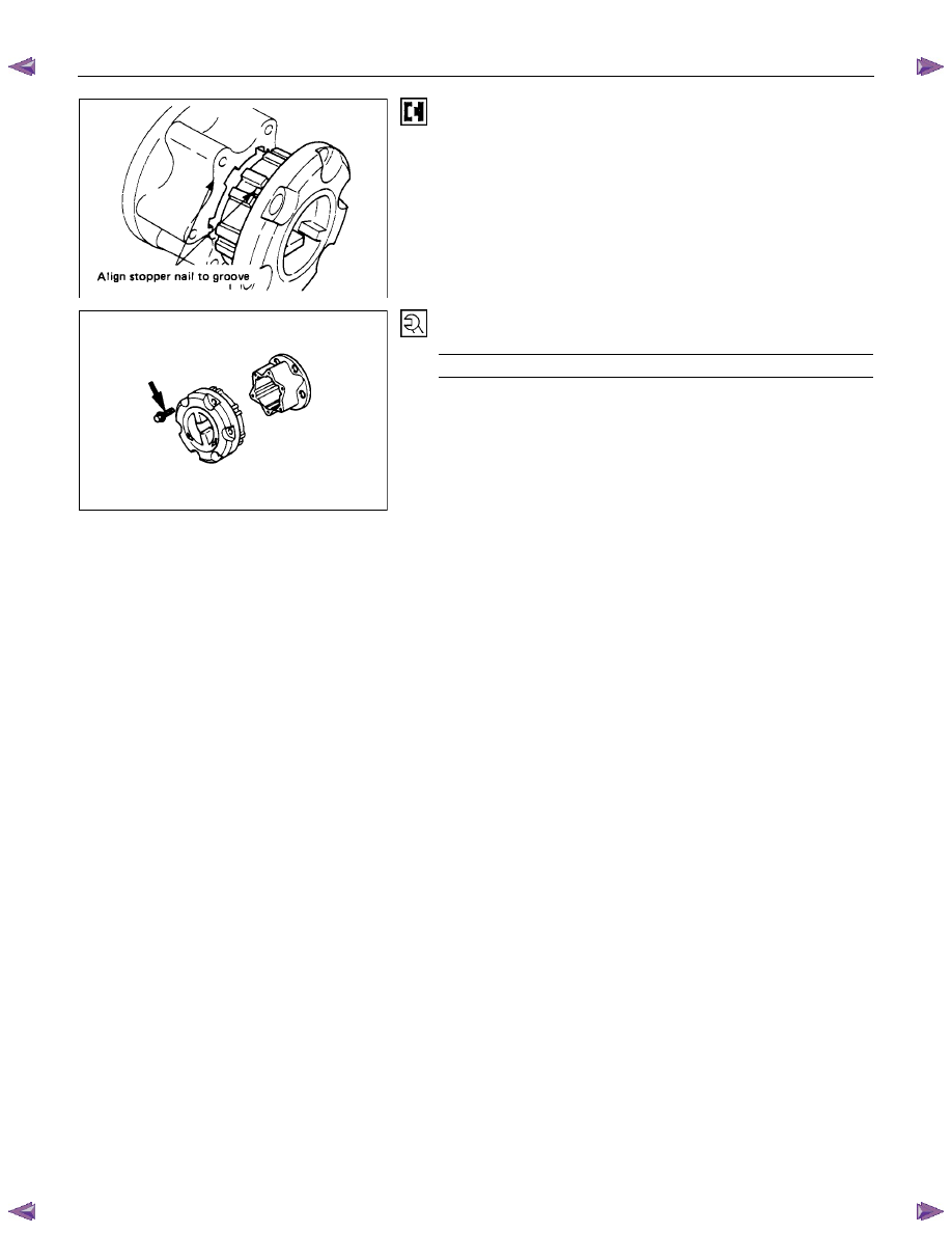
23. Snap Ring and Shims
Adjust the clearance between the free wheeling hub body and
the snap ring.
Clearance mm(in)
0 - 0.2 (0 - 0.08)
Adjust Shims Available
mm(in)
0.2, 0.3, 0.5,
1.0
(0.008, 0.0
11, 0.020, 0.039)
4C1-62 FRONT WHEEL DRIVE
24. Cover Assembly
Align stopper nails to grooves of body.
25. Bolt
Torque N
⋅m (kgf⋅m/lb⋅in)
12 (1.2 / 104)
• Refer to SECTION 3E “WHEELS AND TIRES” for wheel
install procedure.
FRONT WHEEL DRIVE 4C1-63
TROUBLESHOOTING
Refer to this Section to quickly diagnose and repair front axle problems. Each troubleshooting chart has three
headings arranged from left to right.
(
1) Checkpoint (2) Trouble Cause (3) Countermeasure
This Section is divided into ten sub-sections:
4×2 Model
1. Wanders and pulls
2. Front wheel shimmy
4×4 Model
1. Oil leak at front axle
2. Oil leak at pinion shaft
3. Noises in front axle drive shaft joint
4. Noises in front axle
5. Wanders and pulls
6. Front wheel shimmy
Propeller shaft
1. Noise
2. Vibration
Нет комментариевНе стесняйтесь поделиться с нами вашим ценным мнением.
Текст