Isuzu KB P190. Manual — part 1139
UNIT REPAIR (JR405E) 7A4-79
40ASSY091
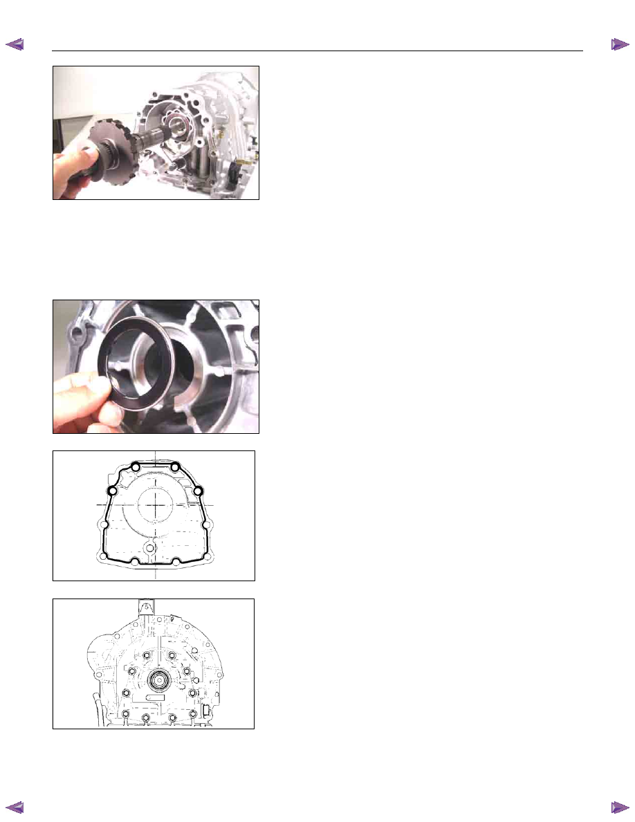
• Push the output shaft into place.
19.Rear extension (2WD) or adapter case (4WD)
• Use the oil seal installer to install the oil seal to the rear
extension (2WD) or adapter case (4WD).
Oil seal installer:
5-8840-2769-0 (2WD)
5-8840-2770-0 (4WD)
41ASSY096
• Install the bearing (with bearing race) to the rear
extension (2WD) or adapter case (4WD).
NOTE:
•••• The black side (bearing race) of the bearing must be
visible.
•••• Apply Vaseline to the bearing.
249L300005
• Apply sealing agent (TB1216B) to the rear extension
(2WD) or adapter case (4WD) contact surfaces.
249L300006
• Install the rear extension (2WD) or adapter case (4WD)
to the transmission case and tighten the 10 bolts to the
specified torque.
Torque: 53 N
⋅⋅⋅⋅m (5.4 kgf⋅⋅⋅⋅m/39 Ib⋅⋅⋅⋅ft)
7A4-80 UNIT REPAIR (JR405E)
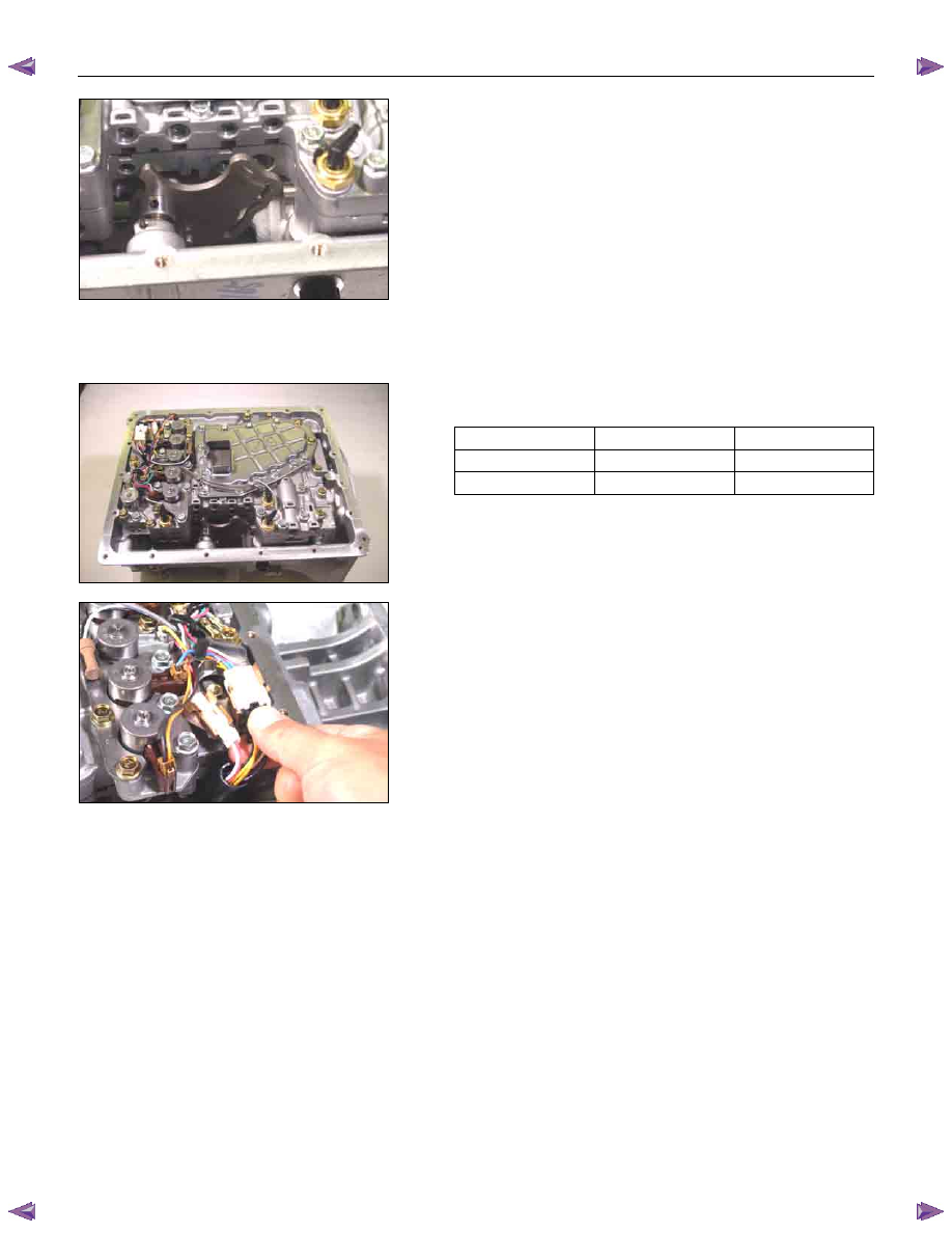
43ASSY119
20.Control valve assembly
• Align the manual valve and the manual plate of the
transmission case.
• Install the control valve assembly and tighten the 12
fixing bolts to the specified torque.
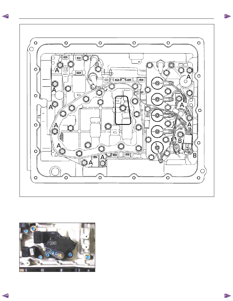
Number of bolts
Length
Color
10 (A)
40 mm (1.57 in)
Gold
2 (B)
30 mm (1.18 in)
Gold
44ASSY121
Torque: 8 N
⋅⋅⋅⋅m (0.8 kgf⋅⋅⋅⋅m/69 Ib⋅⋅⋅⋅in)
45CV29
• Connect the harness assembly and control valve
assembly connectors.
UNIT REPAIR (JR405E) 7A4-81
244L300001
21.Oil pan
• Install a new gasket and the oil pan.
• Tighten the bolts to the specified torque.
Torque: 8 N
⋅⋅⋅⋅m (0.8 kgf⋅⋅⋅⋅m/69 lb⋅⋅⋅⋅in)
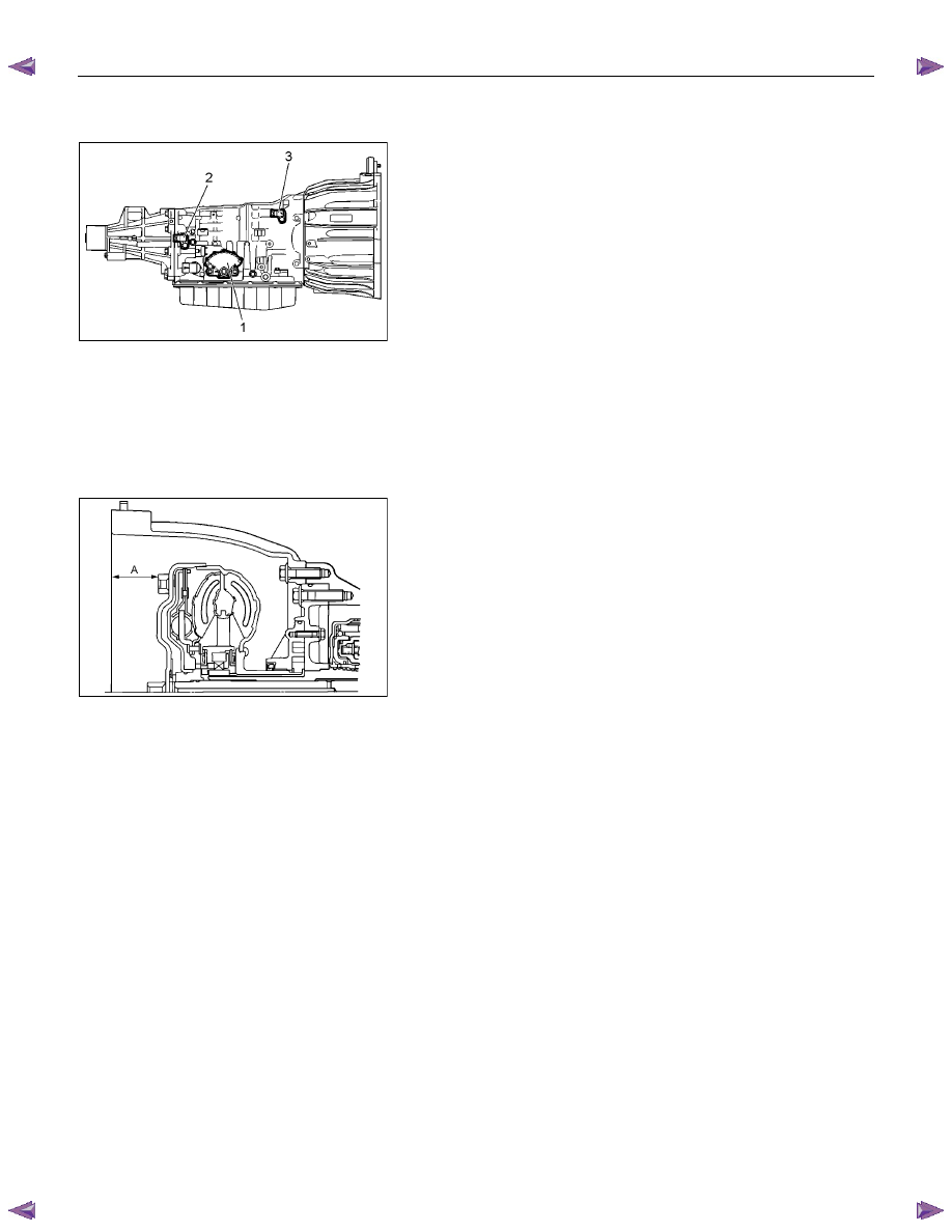
47INH-SW01
22.Inhibitor switch
• Secure the inhibitor switch (1) by hand-tightening the 2
bolts.
• Use the inhibitor switch set plate to align the neutral
holes (manual shaft and inhibitor switch).
Turn the inhibitor switch to adjust it.
Inhibitor switch set plate: 5-8840-2763-0
NOTE:
Inhibitor switch adjustment is very important.
If the inhibitor switch is not correctly adjusted, the
automatic transmission will not function normally.
• Tighten the 2 inhibitor switch bolts to the specified
torque.
7A4-82 UNIT REPAIR (JR405E)
Torque: 6 N
⋅⋅⋅⋅m (0.6 kgf⋅⋅⋅⋅m/52 lb⋅⋅⋅⋅in)
• Remove the holding fixture from the transmission case.
RTW47ASH001001
23.Speed sensor and turbine sensor
• Apply ATF to the new O-rings and install them in the
speed sensor (2) and the turbine sensor (3).
• Install the speed sensor and the turbine sensor. Tighten
the bolt to the specified torque.
Torque: 6 N
⋅⋅⋅⋅m (0.6 kgf⋅⋅⋅⋅m/52 Ib⋅⋅⋅⋅in)
24.Torque converter
• Pour the new ATF into the torque converter.
• Shake the torque converter to thoroughly clean the
inside.
• Drain the ATF from the torque converter.
• Pour the new ATF into the torque converter.
NOTE:
If significant amounts of foreign material (clutch facing,
metallic fragments, etc.) are found in the automatic
transmission at time of disassembly, the existing torque
converter must be replaced with a new one.
RTW47ASH000901
• Install the torque converter.
• Measure the torque converter end play (A).
If the measured value is greater than the specified
minimum, the torque converter is correctly installed.
Torque converter end pay (Minimum): 67 mm (2.64
in)
Нет комментариевНе стесняйтесь поделиться с нами вашим ценным мнением.
Текст