Isuzu KB P190. Manual — part 521

6A-70 ENGINE MECHANICAL (C24SE)
FUEL INJECTION SYSTEM
MAP SENSOR
Removal
1. Disconnect the battery cable.
2. Disconnect the electrical connector from the sensor.
3. Remove the mounting bolts securing the sensor to the
manifold.
4. Remove the sensor from the intake manifold.
Installation
1. Push MAP sensor into the manifold.
2. Install the mounting bolts and tighten them.
3. Connect electrical connector.
4. Connect the battery cable.
Pressure Regulator
Removal
1. Remove vacuum hose.
2. Remove fuel hoses.
3. Remove pressure regulator.
Installation
1. Install pressure regulator.
2. Install fuel hoses.
3. Install vacuum hoses.
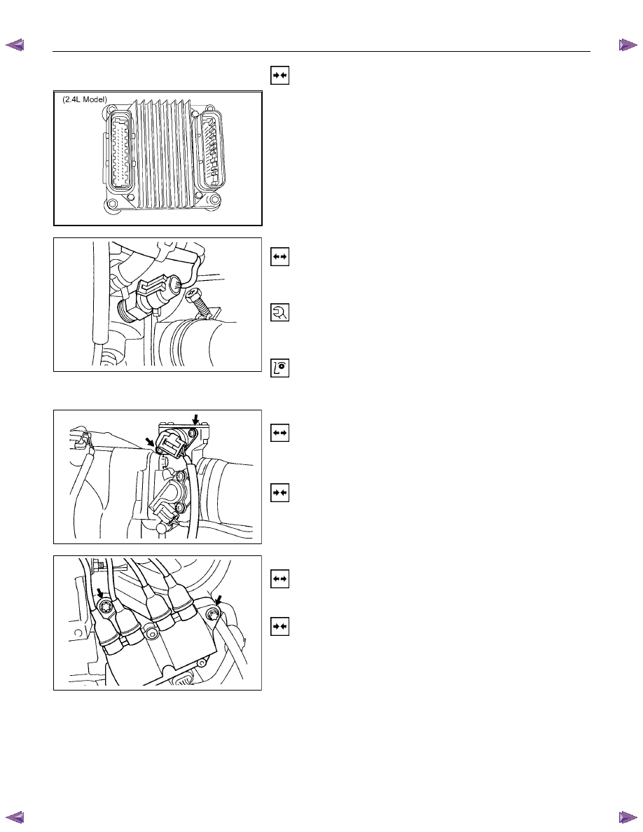
ECM (Engine Control Module)
Removal
(2.4L)
1. Disconnect the ECM connector.
2. Remove the four hex bolts and nuts.
3. Remove the ECM from the ECM bracket on engine.
ENGINE MECHANICAL (C24SE) 6A-71
Installation
(2.4L)
1. Install the ECM to the ECM bracket on engine.
2. Tighten the four screws to the bracket.
3. Connect the connector.
ECT
Removal
1. Remove wiring harness plug and coolant temperature
sensor.
Tighten (Torque)
Temperature sensor to intake pipe - 10 N
⋅m (1.0 kgf⋅m)
Wiring harness plug to temperature sensor
Inspection
Coolant level
Idle Air Control (IAC) Valve
Removal
1. Remove wiring harness plug, hose clamps and idle
speed adjuster.
Installation
1. Install idle speed adjuster, hose clamps and wiring
harness plug.
Ignition Coil
Removal
1. Remove 2 bolts, plug and ignition coil.
Installation
1. Install ignition coil, plug and bolts.
6A-72 ENGINE MECHANICAL (C24SE)
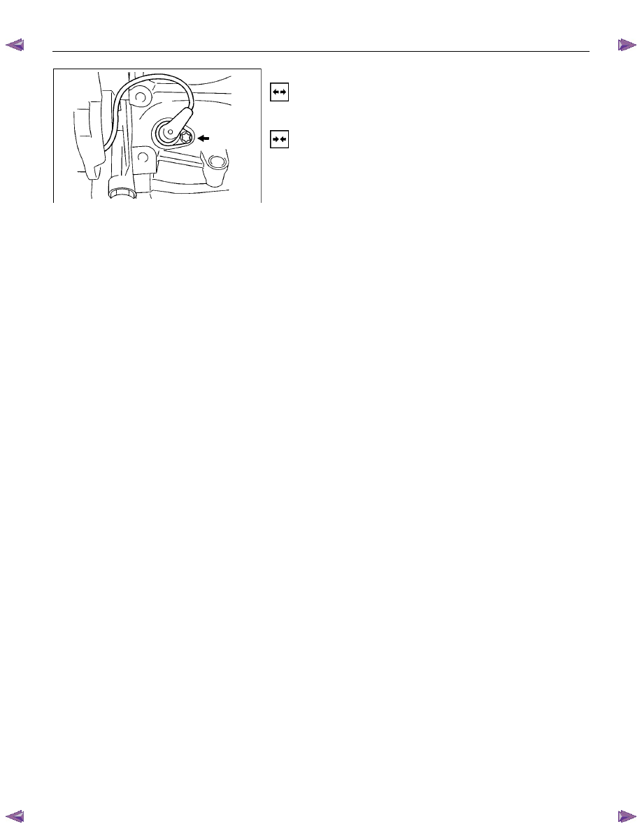
Crank Position Sensor
Removal
1. Remove crank position sensor.
Installation
1. Install crank position sensor.
ENGINE MECHANICAL (C24SE) 6A-73
FUEL INJECTOR
Removal
Caution: To reduce the risk of fire and personal injury, it is
necessary to relieve the fuel system pressure before
servicing the fuel system components.
Caution: After relieving the fuel system pressure, a small
amount of fuel may be released when servicing fuel lines
or connections. Reduce the chance of personal injury by
covering the fuel line fitting with a shop towel before
disconnecting the fittings. The towel will absorb any fuel
that may leak out. When the disconnect is completed,
place the towel in an approved container.
1. Depressurize the fuel system.
2. Disconnect the fuel inlet.
3. Disconnect the fuel return line.
4. Remove the fuel rail from the intake manifold.
5. Remove the fuel injector from the fuel rail by disengaging
claws.
Installation
1. Install the fuel injector to the fuel rail by engaging claws.
2. Install the fuel rail to the intake manifold.
3. Connect the fuel return line firmly.
4. Connect the fuel supply line firmly.
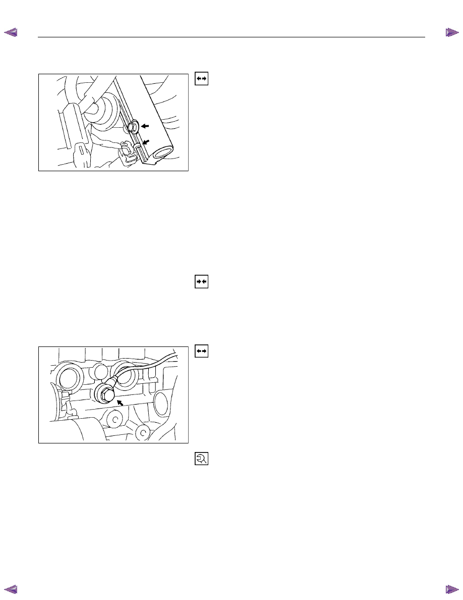
Knock sensor
Removal
1. Remove fixing bolts.
2. Disconnect the connector at the other side.
Tighten (Torque)
Oxygen sensor in exhaust pipe - 30N
⋅m (3.1 kgf⋅m)
When re-using, insert oxygen sensor.
Нет комментариевНе стесняйтесь поделиться с нами вашим ценным мнением.
Текст