Isuzu KB P190. Manual — part 572

6E–118
ENGINE DRIVEABILITY AND EMISSIONS
P1167
D
Fuel Supply System Rich During
Deceleration Fuel Cutoff
1. No DTC relating to MAP sensor, TPS,
EVAP purge, ECT sensor, CKP sensor,
VSS, injector control circuit and ignition
control circuit.
2. O
2
sensor bank 1 output voltage is more
than 550mV in deceleration fuel cutoff
mode.
No fail-safe function.
O
2
sensor output voltage is below 550mV.
1. Sensor harness open or short to ground
circuit.
2. O
2
sensor malfunction.
3. MAF sensor output is incorrect.
4. Air intake line malfunction.
5. IAC valve malfunction.
6. Low fuel pressure.
7. Injector malfunction.
8. EVAP purge solenoid valve malfunction.
9. Ignition system malfunction.
10. Spark plug malfunction.
11. ECM malfunction.
J2-6/
J2-21
P1171
D
Fuel Supply System Lean During Power
Enrichment
1. No DTC relating to MAP sensor, TPS,
EVAP purge, ECT sensor, CKP sensor,
VSS, injector control circuit and ignition
control circuit.
2. Engine coolant temperature is more than
60deg. C.
3. Mass air flow is below 13.5m/s.
4. O
2
sensor bank 1 output voltage is below
350mV in power enrichment mode.
No fail-safe function.
O
2
sensor output voltage is more than
350mV.
1. Sensor harness open or short to ground
circuit.
2. O
2
sensor malfunction.
3. MAF sensor output is incorrect.
4. Air intake line malfunction.
5. IAC valve malfunction.
6. Low fuel pressure.
7. Injector malfunction.
8. ECM malfunction.
J2-6/
J2-21
P1625
B
ECM System Reset
ECM reset has occurred other than “On”.
Engine control disabled.
Memory are is OK.
1. Electrical interference.
2. Magnetic interference.
3. ECM malfunction.
-
P1626
-
Immobilizer No Signal
No response from immobilizer control unit.
1. Engine does not start.
2. Check engine lamp flash.
No recovery.
1. ECM and immobilizer control unit
communication circuit open circuit, short to
ground circuit or short to voltage circuit.
2. ECM malfunction.
3. Immobilizer control unit malfunction.
4. Transponder key malfunction.
J2-23/
J2-32
P1631
-
Immobilizer Wrong Signal
Received response is not correct.
1. ECM malfunction.
2. Immobilizer control unit malfunction.
3. Transponder key malfunction.
-
P1648
-
Wrong Security Code Entered
Received incorrect security code.
1. ECM malfunction.
2. Immobilizer control unit malfunction.
3. Transponder key malfunction.
-
P1649
-
Immobilizer Function Not Programmed
Immobilizer function is not programmed in the
ECM.
ECM malfunction.
-
P1693
B
Tachometer Output Low Voltage
Tacho output circuit short to ground circuit.
No fail-safe function.
Tacho output circuit is correct condition.
1. Tacho output circuit short to ground circuit.
2. Poor connector connection.
3. ECM malfunction.
J2-25
Code
Type
DTC Name
DTC Setting Condition
Fail-Safe (Back Up)
Recovery Condition
Related Failure Parts
Related
ECM
Pin No.
ENGINE DRIVEABILITY AND EMISSIONS
6E–119
DIAGNOSTIC TROUBLE CODE (DTC) P0107 MANIFOLD ABSOLUTE
PRESSURE CIRCUIT LOW INPUT
Condition for setting the DTC and action taken when the DTC sets
Circuit Description
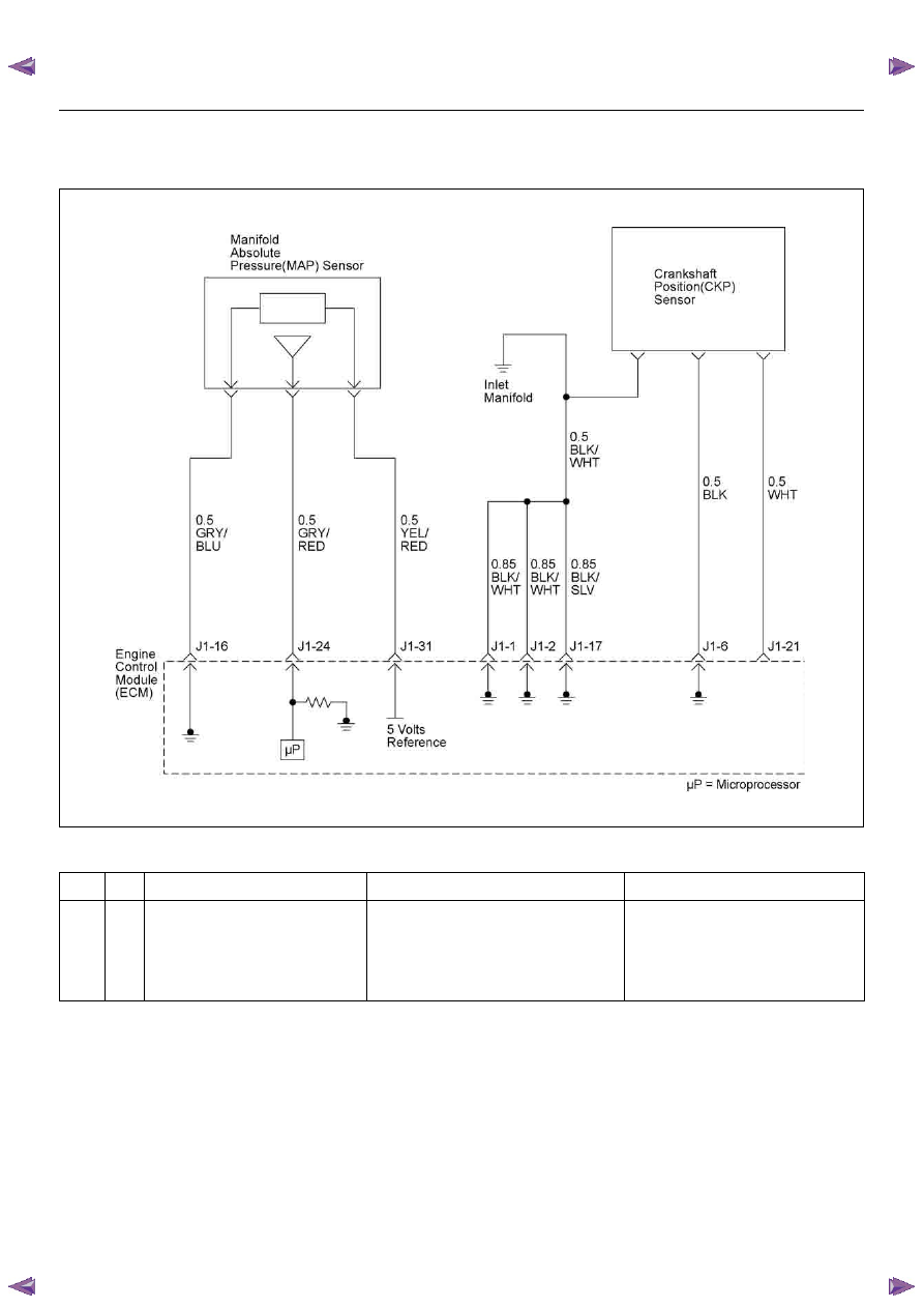
The manifold absolute pressure (MAP) sensor responds
to changes in intake manifold pressure. The MAP
sensor signal voltage to the engine control module
(ECM) varies from below 2 volts at idle (low manifold
pressure) to above 4 volts with the ignition ON, engine
not running or at wide-open throttle (high manifold
pressure).
A “speed density” method of determining engine load is
used on the 2.4L engine. This is calculated using inputs
from the MAP sensor, the CKP Sensor, and the Intake
Air Temperature (IAT) sensor. The MAP sensor is the
main sensor used in this calculation, and measuring
engine load is its main function.
The ECM monitors the MAP signals for voltages outside
the normal range (10-104 kPa) of the MAP sensor. If the
ECM detects a MAP signal voltage that is excessively
low, Diagnostic Trouble Code P0107 will be set.
Diagnostic Aids
Check for the following conditions:
• Poor connection at ECM - Inspect harness
Code
Type
DTC Name
DTC Setting Condition
Fail-Safe (Back Up)
P0107
A
Manifold Absolute Pressure Circuit
Low Input
1. No DTC relating to TPS.
2. Throttle position is more than 0% if engine
speed is below 1000rpm, or throttle posi-
tion more than 5% if engine speed is more
than 1000rpm.
3. MAP sensor output is below 12kPa.
The ECM uses default manifold absolute
pressure value based on engine speed
and throttle position.
6E–120
ENGINE DRIVEABILITY AND EMISSIONS
connectors for backed-out terminals, improper
mating, broken locks, improperly formed or damaged
terminals, and poor terminal-to-wire connection.
• If these codes are also set, it could indicate a
problem with the 5 Volt reference circuit.
• Damaged harness - Inspect the wiring harness for
damage, short to ground, short to battery positive,
and open circuit. If the harness appears to be OK,
observe the MAP display on the Tech 2 while moving
connectors and wiring harnesses related to the
sensor. A change in the display will indicate the
location of the fault.
Diagnostic Trouble Code (DTC) P0107
Manifold Absolute Pressure Circuit Low Input
Step
Action
Value(s)
Yes
No
1
Was the “On-Board Diagnostic (OBD) System Check”
performed?
—
Go to Step 2
Go to On Board
Diagnostic
(OBD) System
Check
2
1. Connect the Tech 2.
2. Review and record the failure information.
3. Select “F0: Read DTC Infor By Priority” in “F0:
Diagnostic Trouble Code”.
Is the DTC P0107 stored as “Present Failure”?
—
Go to Step 3
Refer to
Diagnostic Aids
and Go to Step
3
3
1. Using the Tech2, ignition “On” and engine “Off”.
2. Select “Clear DTC Information” with the Tech2 and
clear the DTC information.
3. Operate the vehicle and monitor the “F5: Failed
This Ignition” in “F2: DTC Information”.
Was the DTC P0107 stored in this ignition cycle?
—
Go to Step 4
Refer to
Diagnostic Aids
and Go to Step
4
4
Check for poor/faulty connection at the MAP sensor or
ECM connector. If a poor/faulty connection is found,
repair as necessary.
Was the problem found?
—
Verify repair
Go to Step 5
5
Visually check the MAP.
Was the problem found?
—
Go to Step 9
Go to Step 6
6
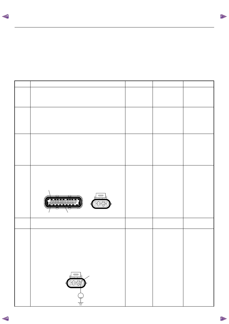
Using the DVM and check the MAP sensor power
supply circuit.
1. Ignition “On”, engine “Off”.
2. Disconnect the MAP sensor connector.
3. Check the circuit for open or short to ground
circuit.
Was the DVM indicated specified value?
Approximately
5.0V
Go to Step 8
Go to Step 7
16
31
24
E85
E60(J1)
V
E85
3
ENGINE DRIVEABILITY AND EMISSIONS
6E–121
7
Repair the open or short to ground circuit between the
ECM and MAP sensor
Was the problem solved?
—
Verify repair
Go to Step 11
8
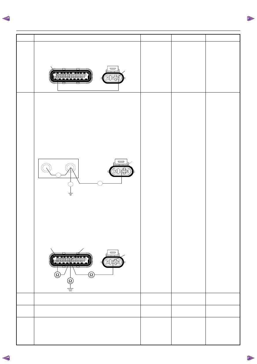
Using the DVM and check the MAP sensor signal
circuit.
Breaker box is available:
1. Ignition “Off”, engine “Off”.
2. Install the breaker box as type A. (ECM
disconnected) Refer to 6E-88 page.
3. Disconnect MAP sensor connector.
4. Check the circuit for open, short to sensor ground
or short to ground circuit.
Was the problem found?
Breaker box is not available:
1. Ignition “Off”, engine “Off”.
2. Disconnect the MAP sensor connector and ECM
connector.
3. Check the circuit for open, short to sensor ground
or short to ground circuit.
Was the problem found?
—
Repair faulty
harness and
verify repair
Go to Step 9
9
Substitute a known good MAP sensor and recheck.
Was the problem solved?
—
Go to Step 10
Go to Step 11
10
Replace the MAP sensor.
Is the action complete?
—
Verify repair
—
11
Is the ECM programmed with the latest software
release?
If not, download the latest software to the ECM using
the “SPS (Service Programming System)”.
Was the problem solved?
—
Verify repair
Go to Step 12
Step
Action
Value(s)
Yes
No
31
3
E85
E60(J1)
J1-16
J1-24
Ω
Breaker Box
Ω
E-85
Ω
2
16
24
2
E85
E60(J1)
Нет комментариевНе стесняйтесь поделиться с нами вашим ценным мнением.
Текст