Isuzu KB P190. Manual — part 988
Automatic Transmission – 4L60E – On-vehicle Servicing
Page 7C4–39
10
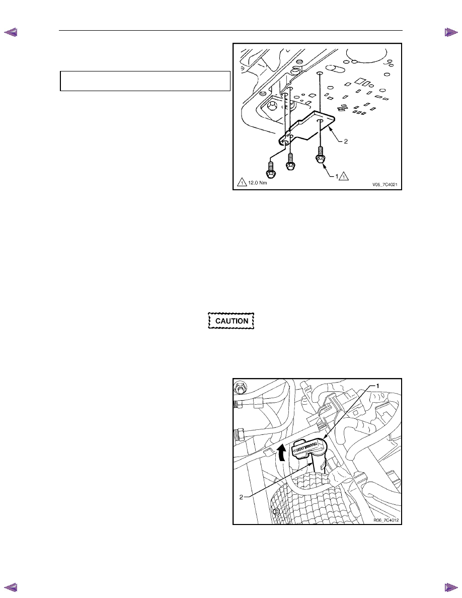
Reinstall the plate (2) supporting the spacer plate and
tighten the three attaching bolts (1) to the correct
torque specification.
Spacer plate support plate attaching
bolt torque specification . . . . . . . . . .12.0 Nm
11
Reinstall the control valve body, refer to
3.14
Control Valve Body.
12
Reinstall the Oil pan and filter and fill the transmission
with the recommended automatic transmission fluid,
refer to 3.1 Fluid Change and Filter Replacement.
13
Lower vehicle to the ground.
14
Road test until the transmission has reached operating
temperature. Re-check the fluid level and for any fluid
leaks from the oil pan area, refer to 2.1 Transmission
Fluid.
Figure 7C4 – 55
3.16 Filler Tube and Breather Hose
Remove
N O T E
The breather hose and/or vent pipe can be
removed independently from the filler tube as
described in step 7.
Disconnection of the battery affects certain
vehicle electronic systems. Refer to 6D1-3
Battery, before disconnecting the battery.
1
Disconnect the battery ground lead.
2
Release the lock down lever (1) and remove the
transmission fluid level indicator from the filler tube (2).
Figure 7C4 – 56
3
Remove the bolt (1) attaching the filler tube (2) to the side of the right-hand cylinder head, refer to Figure 7C4 – 57.
4
Using a twisting and pulling motion, remove the filler tube from the seal (3) in the transmission case.
Automatic Transmission – 4L60E – On-vehicle Servicing
Page 7C4–40
5
Remove the filler tube from the engine compartment.
6
Remove the filler tube seal from the transmission case and discard.
7
If the breather hose needs to be replaced proceed as follows:
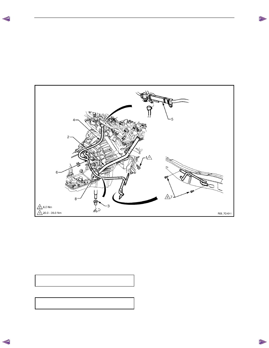
a
unclip the breather hose (4) from the harness channel (5).
b
Remove the transmission support and lower the rear of the transmission sufficiently to get access to the
breather hose, refer to 3.7
Transmission Support and Mount.
c
Disconnect the breather hose from the T-joint (6) and the top of the transmission case and remove.
d
If required, remove the two bolts (7) attaching the brackets of the vent pipe (8) to the chassis, disconnect from
the T-joint and remove the vent pipe.
Figure 7C4 – 57
Reinstall
Reinstallation of the transmission filler tube and/or the breather hose is the reverse of the removal procedure, noting the
following:
1
Smear a new filler tube seal with clean transmission fluid and fit it to the transmission case.
2
Ensure the transmission breather hose and the harness are secured to the filler tube lower bracket.
3
Tighten the bolt attaching the filler tube bracket to the correct torque specification.
Filler tube bracket attaching bolt
torque specification . . . . . . . . . 20.0 – 35.0 Nm
4
If required, tighten the two bolts attaching the vent pipe bracket to the chassis to the correct torque specification.
Vent pipe attaching bolt
torque specification . . . . . . . . . . . ..6.0 Nm
Automatic Transmission – 4L60E – On-vehicle Servicing
Page 7C4–41
3.17 Transmission
Cooler
Line/Hose
Assemblies
Remove
1
Disconnect the transmission cooler hose/line
assemblies from the radiator quick connect fittings as
follows:
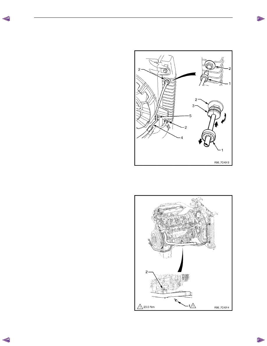
a
Pull back the verifier disc (1) from the quick
connect fitting (2) and slide it back along the line.
b
Open the release tool, Tool No J-41623-B (3),
slip it over the cooler line to be disconnected
from the radiator, ahead of the verifier disc.
c
Slide the release tool along the cooler line and
engage it with the quick-connect fitting.
d
While pushing inwards, rotate clockwise the
release tool about one sixth of a turn to release
the spring clip holding the cooler line.
e
With the release tool held in this position, pull
back on the cooler line to release it.
f
Plug the openings to prevent fluid loss and/or
contamination.
g
Repeat the procedure to remove the remaining
cooler line.
N O T E
If the spring clip and/or O-ring seal in the quick-
connect fitting is damaged during the removal
process, the complete fitting must be replaced.
2
Unclip the outlet cooler line (4) from the radiator fan
shroud (5).
Figure 7C4 – 58
3
Remove the screw (1) attaching the transmission
cooler line bracket (2) to the right-hand side of the
engine.
Figure 7C4 – 59
4
Remove the transmission support, refer to 3.7
Transmission Support and Mount.
Automatic Transmission – 4L60E – On-vehicle Servicing
Page 7C4–42
5
Carefully lower the rear of the transmission sufficiently to get access to the cooler lines.
6
Place a suitable sized drip tray underneath the transmission.
7
With the rear of the transmission lowered, disconnect
the cooler lines from the transmission, as follows:
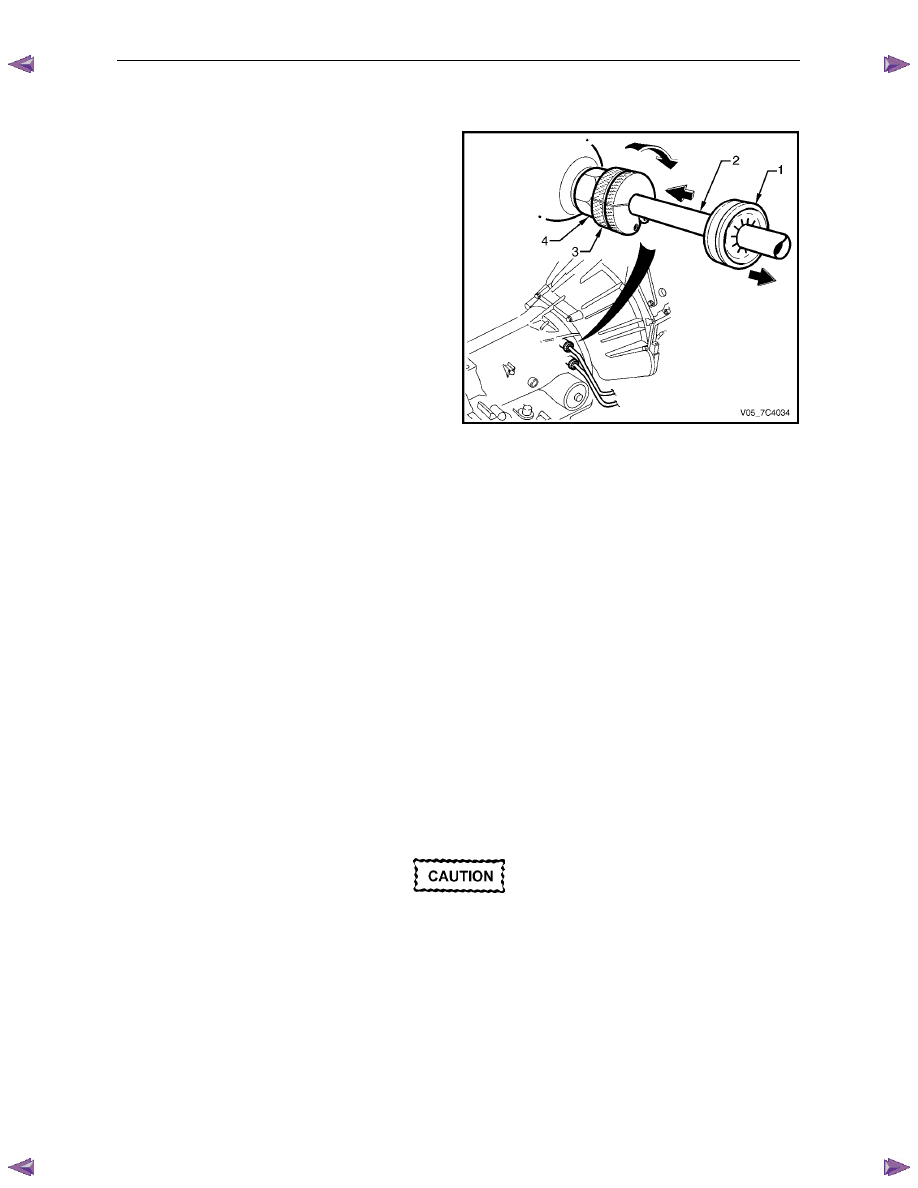
a
Pull back the verifier disc (1) to release it and
slide it back along the cooler line (2).
b
Open the release tool, Tool No J-41623-B (3),
slip it over the cooler line to be disconnected
from the transmission, ahead of the verifier disc.
c
Slide the release tool along the cooler line and
engage it with the quick-connect fitting (4).
d
While pushing inwards, rotate clockwise the
release tool about one sixth of a turn to release
the spring clip holding the cooler line.
e
With the release tool held in this position, pull
back on the cooler line to release it.
f
Plug all openings to prevent fluid loss and/or
contamination.
g
Repeat this process with the remaining cooler
line.
N O T E
If the spring clip and/or O-ring seal in the quick-
connect fitting is damaged during the removal
process, the complete fitting must be replaced.
Figure 7C4 – 60
8
Carefully remove the two cooler lines from the vehicle.
9
As required, separate the two cooler lines by removing the bracket and the two clips.
Reinstall
1
On the transmission end, ensure the spring clip and/or O-ring seal in each quick-connect fitting is not damaged,
replace the complete fitting if required.
2
If required, fit the bracket and the two clips to attach the transmission two cooler lines together.
3
Position the cooler lines in place, attach the cooler line bracket (2) with the screw (1) hand tight to the right-hand
side of the engine, refer to Figure 7C4 – 59.
4
Remove the plugs from the cooler lines and transmission fittings and wipe all exposed parts clean.
5
At the transmission end, smear the fluid lines rear fittings with clean automatic transmission fluid and push the
quick-connect fittings together.
If the verifier disc does not clip into place, the
quick-connect fitting is not engaged, rectify
as required.
6
As a security check, push and clip each verification disc into place over the quick-connect fittings. If difficulty is
experienced, repeat the installation process until the verification disc can be clipped into place over the
transmission quick-connect fitting.
7
Reinstall the transmission support, refer to 3.7 Transmission Support and Mount.
8
Remove the plugs from the cooler lines and radiator fittings and wipe all exposed parts clean.
9
At the radiator end, smear the fluid lines fittings with clean automatic transmission fluid and push the quick-connect
fittings together, refer to Figure 7C4 – 58.
Нет комментариевНе стесняйтесь поделиться с нами вашим ценным мнением.
Текст