Isuzu KB P190. Manual — part 986
Automatic Transmission – 4L60E – On-vehicle Servicing
Page 7C4–31
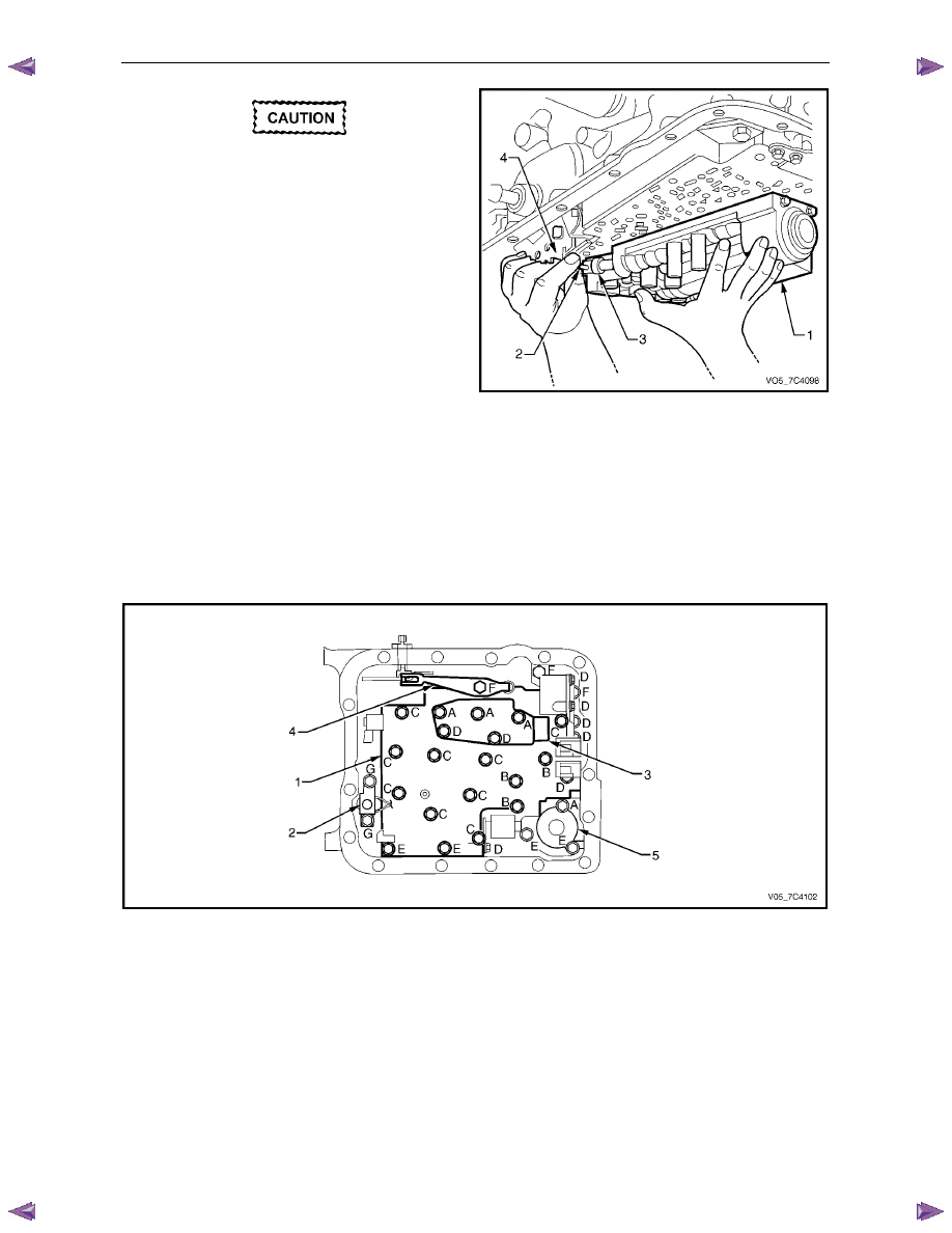
Keep the control valve body level when
lowering it to prevent the loss of the
checkballs located in the body passages.
5
Carefully lower the control valve body (1) from the
transmission case. As the valve body is being lowered,
rotate it slightly to disconnect the manual valve link (2)
from the manual valve (3) and remove the control
valve body.
6
Remove the manual valve link from the inner detent
lever (4).
Figure 7C4 – 39
Reinstall
Different bolt sizes are used to attach the control valve body and components, Figure 7C4 – 40 shows the location of the
attachment bolts with the letters referring to their dimensions.
N O T E
For clarity, the control valve body harness is not
shown in the illustration.
Figure 7C4 – 40
Legend
1
Control Valve Body
2
Torque Converter Clutch (TCC) Solenoid
3
Transmission Fluid Pressure (TFP) Manual Valve Position
Switch
4
Manual Detent Spring
5
1 – 2 Accumulator Cover
A
Bolt M6 x 1.00 x 65.0
B
Bolt M6 x 1.00 x 54.4
C
Bolt M6 x 1.00 x 47.5
D
Bolt M6 x 1.00 x 18.0
E
Bolt M6 x 1.00 x 35.0
F
Bolt M6 x 1.25 x 20.0
G
Bolt M6 x 1.00 x 12.0
1
Ensure the spacer plate gasket is in a satisfactory condition, replace as required, refer to 3.15 Spacer Plate, Check
Balls, Filter Screens and 3 – 4 Accumulator.
Automatic Transmission – 4L60E – On-vehicle Servicing
Page 7C4–32
2
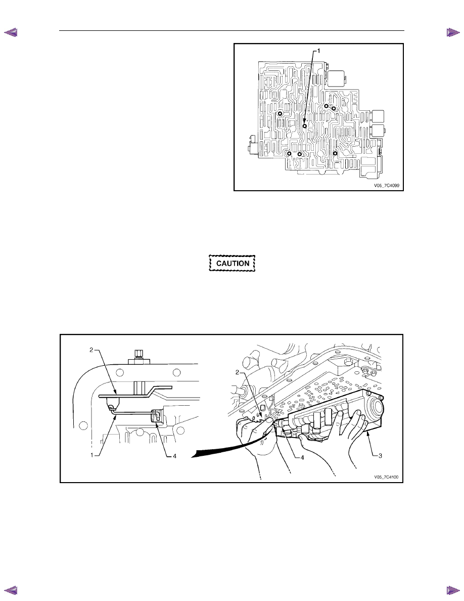
If required, reinstall the seven checkballs (1) in the
control valve body securing them with petroleum jelly.
Figure 7C4 – 41
3
Reinstall the manual valve link (1) to the inner detent lever (2), refer to Figure 7C4 – 42.
4
While supporting the control valve body (3), rotate it slightly and connect the manual valve link with the manual
valve (4).
Take care not to damage the two filter screens
attached to the spacer plate during this
operation.
5
Position the manual valve forward to retain the link connection and carefully raise the valve body into position.
6
Check if the manual valve link is correctly reinstalled in the detent lever and manual valve.
Figure 7C4 – 42
Automatic Transmission – 4L60E – On-vehicle Servicing
Page 7C4–33
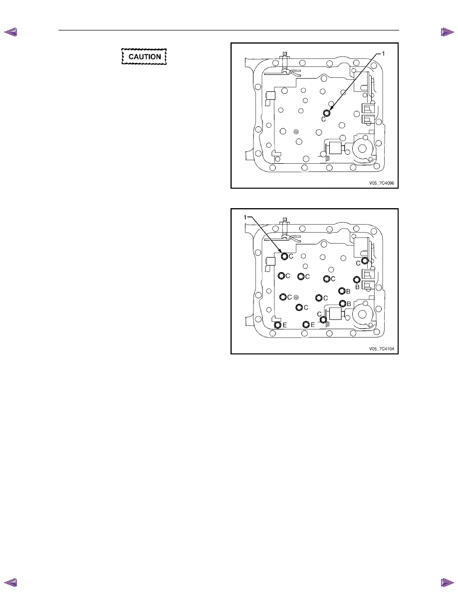
When reinstalling the bolts throughout this
procedure, ensure to use the correct bolt
dimension in each location.
7
Reinstall one bolt (1) (M6 X 1.0 X 47.5) hand tight in
the centre of the control valve body to hold it in place,
at location C as shown.
Figure 7C4 – 43
8
Reinstall hand tight only, the remainder of the fourteen
bolts (1) attaching the control valve body directly.
N O T E
Refer to Figure 7C4 – 40 for each bolt dimension
and corresponding location.
Figure 7C4 – 44
Automatic Transmission – 4L60E – On-vehicle Servicing
Page 7C4–34
9
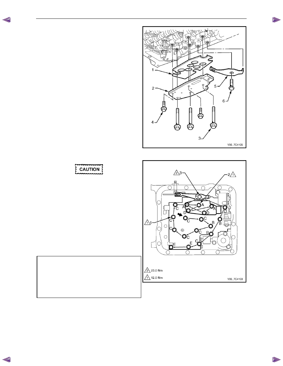
Fit a new shield (1) to the transmission fluid pressure
(TFP) manual valve position switch (2) and reinstall to
the control valve body.
N O T E
Refer to Figure 7C4 – 40 for bolt dimension and
corresponding location.
10
Reinstall the three long bolts (3) and the two short
bolts (4) hand tight only.
11
Reinstall the manual detent spring (5) and the
attaching bolt (6) hand tight only.
Figure 7C4 – 45
The control valve body bolts must be
tightened in an outward spiral starting from
the centre. Failure to follow this pattern may
distort the valve body causing the valves to
jam in their bores.
12
Follow the sequence starting from the centre as shown
by the arrows to tighten the following bolts to the
correct torque specification:
•
fourteen bolts (1) attaching the control valve
body,
•
five bolts (2) attaching the transmission fluid
pressure (TFP) manual valve position switch and
•
one bolt (3) attaching the manual detent spring.
Control valve body attaching bolt
torque specification . . . . . . . . . . . 12.0 Nm
Transmission fluid pressure (TFP)
manual valve position switch attaching
bolt torque specification . . . . . . . . . .12.0 Nm
Manual detent spring attaching bolt
torque specification . . . . . . . . . . . 23.0 Nm
13
Reinstall the control valve body harness , refer to
3.13
Control Valve Body Harness.
Figure 7C4 – 46
Нет комментариевНе стесняйтесь поделиться с нами вашим ценным мнением.
Текст