Isuzu KB P190. Manual — part 1111
7A2-160 TRANSMISSION CONTROL SYSTEM (JR405E)
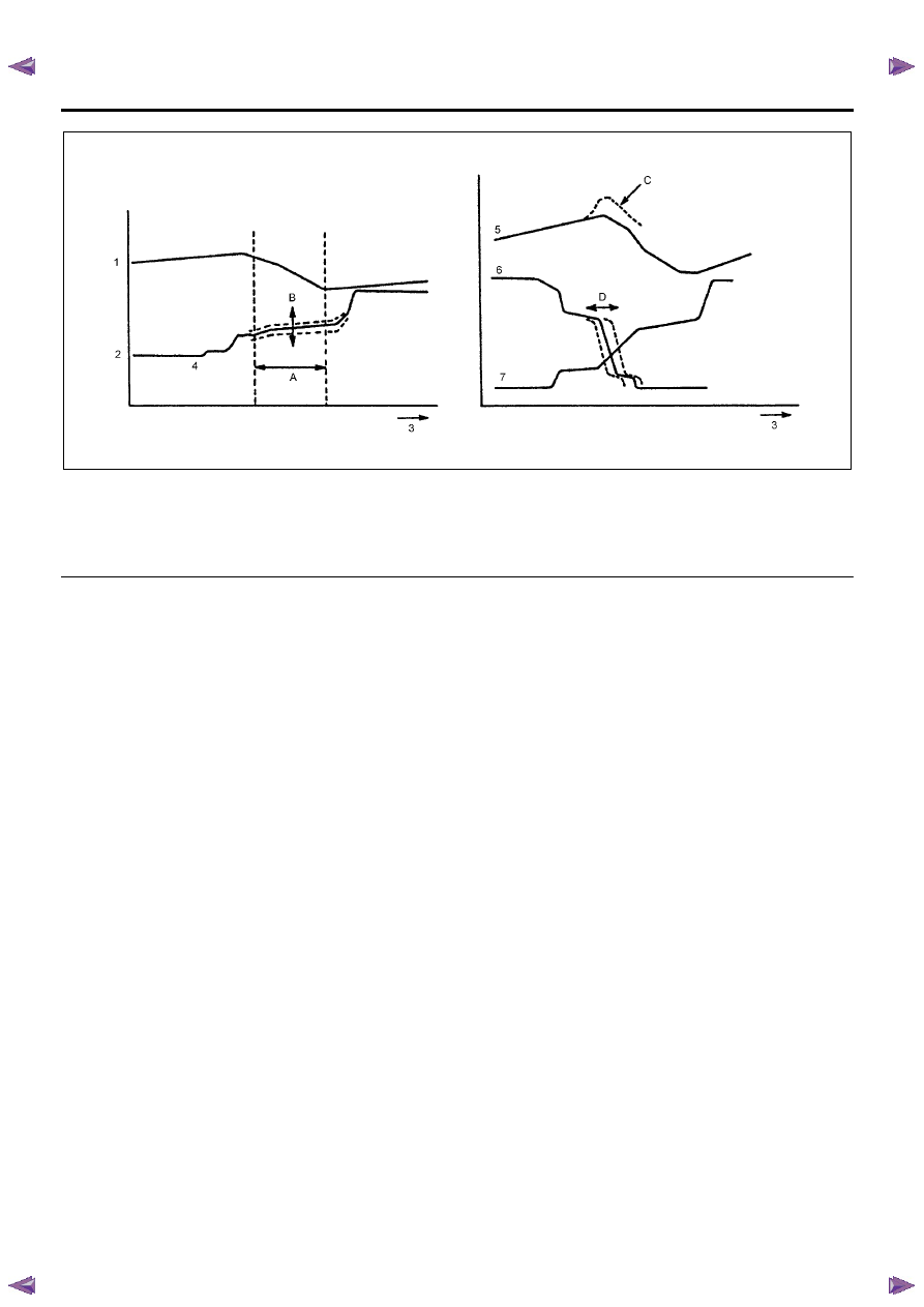
Legend
1. Input shaft speed
2. Transmission fluid pressure
3. Time
4. Clutch engagement fluid pressure
5. Engine speed
6. Disengagement side clutch fluid pressure
7. Engagement side clutch fluid pressure
Transmission fluid pressure control timing is optimally
corrected at the time of clutch engagement and
disengagement. It is controlled to bring the shift time to
the value preset to the TCM, and compensate for the
changes in engine performance and transmission
characteristics. When the gear is shifted, the clutch
pressure (B) is optimally corrected so that the shift time
(A) is as close to the target value preset to the TCM.
The variation in the engine performance and changes
to transmission characteristics which occur with time,
can be compensated for based on the past shift results.
When the clutch is operated to shift the gear, the time
of the clutch fluid pressure release (D) on the
disengagement side is optimally corrected so that the
change of the engine speed (C) is optimum.
Notice: When the battery terminal is disconnected, the
contents of learning are cleared and as a result the shift
shock may increase. After the vehicle has traveled,
learning is repeated and the shock decreases
gradually.
TRANSMISSION CONTROL SYSTEM (JR405E) 7A2-161
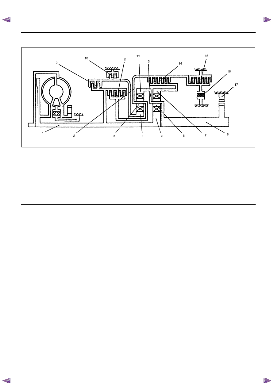
Transmission Power Flow Description
Legend
1. Input shaft
2. Front planetary carrier
3. Front pinion gear
4. Front sun gear
5. Rear sun gear
6. Rear pinion gear
7. Rear internal gear
8. Output shaft
9. Reverse clutch
10. 2-4 brake
11. High clutch
12. Front internal gear
13. Rear planetary carrier
14. Low clutch
15. Low & reverse brake
16. Low one-way clutch
17. Parking pawl
Construction Parts
The JR405E consists of two sets of planetary gears,
three multiple plate clutches, two multiple plate brakes
and one one-way clutch.
High Clutch
High clutch (11) connects the input shaft (1) to the front
planetary carrier (2). It is engaged at 3rd and 4th gear.
Low Clutch
Low clutch (14) connects the front planetary carrier (2)
to the rear internal gear (7). It is engaged at 1st, 2nd
and 3rd gear.
Reverse Clutch
Reverse clutch (9) connects the input shaft (1) to the
front sun gear (4). It is engaged at reverse gear.
Low One-way Clutch
Low one-way clutch (16) allows the front planetary
carrier (2) to turn forward (clockwise) but locks to
opposite direction (counterclockwise). It is operative
when accelerating.
Low & Reverse Brake
Low & reverse brake (15) locks the front planetary
carrier (2). It is engaged in L range and reverse gear.
2-4 Brake
2-4 brake (10) locks the front sun gear (4). It is
engaged at 2nd and 4th (O/D) gear.

7A2-162 TRANSMISSION CONTROL SYSTEM (JR405E)
Parking
Legend
1. Input shaft
2. Front planetary carrier
3. Front pinion gear
4. Front sun gear
5. Rear sun gear
6. Rear pinion gear
7. Rear internal gear
8. Output shaft
9. Reverse clutch
10. 2-4 brake
11. High clutch
12. Front internal gear
13. Rear planetary carrier
14. Low clutch
15. Low & reverse brake
16. Low one-way clutch
17. Parking pawl
Although the driving force of the input shaft (1) is
transmitted to the rear sun gear (5) and reverse & high
clutch drum, the driving force is not transmitted to the
output shaft (8) since all of the clutches and brakes are
not engaged. Therefore, the vehicle can move in this
condition. However, since the output shaft (8) is
mechanically locked with the parking pawl (17), the rear
planetary carrier (13) and front internal gear (12) are
locked. For this reason, the vehicle does not move.

TRANSMISSION CONTROL SYSTEM (JR405E) 7A2-163
Neutral
Legend
1. Input shaft
2. Front planetary carrier
3. Front pinion gear
4. Front sun gear
5. Rear sun gear
6. Rear pinion gear
7. Rear internal gear
8. Output shaft
9. Reverse clutch
10. 2-4 brake
11. High clutch
12. Front internal gear
13. Rear planetary carrier
14. Low clutch
15. Low & reverse brake
16. Low one-way clutch
17. Parking pawl
Although the driving force of the input shaft (1) is
transmitted to the rear sun gear (5) and reverse & high
clutch drum, the driving force is not transmitted to the
output shaft (8) since all of the clutches and brakes are
not engaged. Therefore, the vehicle can move in this
condition.
Нет комментариевНе стесняйтесь поделиться с нами вашим ценным мнением.
Текст