Isuzu KB P190. Manual — part 1110
7A2-156 TRANSMISSION CONTROL SYSTEM (JR405E)
Gearshift Control & Shift Map Selection
The TCM commands each shift solenoid valve based
on the traveling mode switch (power drive/ 3rd start),
transmission range switch, the vehicle speed, the
accelerator pedal angle and other input signals, to
control the optimum gear position automatically. Shift
features have been set up to the TCM as shift map; the
normal mode is suited to normal travel, and the power
mode is used when the vehicle is loaded or the speed
accelerated. In addition, shift features used only for
high transmission fluid temperature, hill climbing, and
downward travel have been set up to the TCM. These
are automatically switched depending on the driving
conditions. When the transmission fluid temperature is
lower than 10
°C (50°F), gearshift from the 3rd to the
4th is inhibited.
Shift Map
The TCM selects either of the following shift map
depending on the driving conditions.
High Temperature Mode
Condition for setting the high temperature mode shift
map;
• Transmission fluid temperature is more than 122
°C
(252
°F) for 10 seconds.
Condition for canceling the high temperature mode shift
map;
• Transmission fluid temperature is less than 115
°C
(239
°F) for 10 seconds
Notice: High temperature mode may be set with
driving conditions other than the setting condition met
in order to protect from a thermal damage.
3rd Start Mode
Condition for setting the 3rd start mode shift map;
All of the following conditions are met:
• 3rd start switch is pressed
• Vehicle speed is less than 11 km/h (7 MPH)
• Transmission fluid is less than 115
°C (239°F)
• Accelerator pedal position is less than 8%
• Selector lever is D range
Condition for canceling the 3rd start mode shift map;
Either of the following condition is met:
• 3rd start switch is pressed again
• Vehicle speed is more than 34 km/h (21 MPH)
• Selector lever is other than D range
4L Mode
Condition for setting the 4L mode shift map;
All of the following conditions are met:
• 4L switch is On
• Vehicle speed is more than 5 km/h (3 MPH)
Condition for canceling the 4L mode shift map;
Either of the following condition is met:
• 4L switch is On
• Vehicle speed is more than 5 km/h (3 MPH)
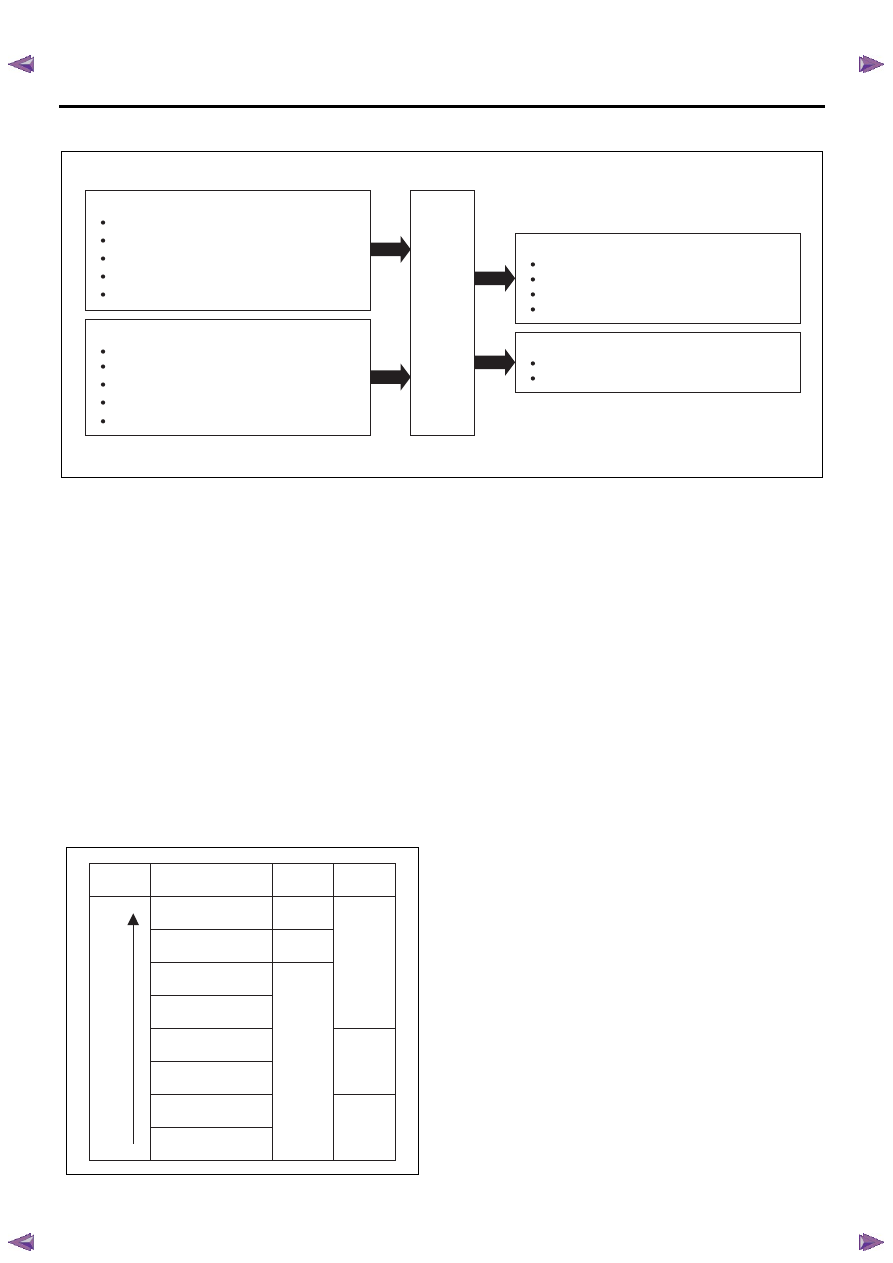
TCM
Sensor inputs
Input shaft speed (ISS) sensor
Output shaft speed (OSS) sensor
Transmission fluid temperature (TFT) sensor
Accelerator pedal position signal (via ECM)
Engine speed signal (via ECM)
Switch inputs
Transmission range (TR) switch
Power drive switch
3rd start switch
Brake pedal switch
4WD low gear signal (via TCCM)
Solenoid valve outputs
Low & reverse brake solenoid valve
2-4 brake solenoid valve
High clutch solenoid valve
Low clutch solenoid valve
Lamp control outputs
Power drive lamp
3rd start lamp
OFF
ON
OFF
ON
OFF
OFF
Low
Priority
Shift map
3rd start
lamp
Power drive
lamp
High temperature mode
3rd start mode
4L mode
Down slope mode when
power drive SW Off
Down slope mode when
power drive SW On
Power drive mode
Up slope mode
Normal mode
High
TRANSMISSION CONTROL SYSTEM (JR405E) 7A2-157
Down Slope Mode
Condition for setting the down slope mode shift map;
All of the following conditions are met:
• Brake pedal switch is depressed
• Accelerator pedal is released
• Vehicle speed is more than 60 km/h (36 MPH)
• Increment of vehicle speed is more than 1 km/h (1
MPH) per second
• Selector lever is D or 3 range
Condition for canceling the down slope mode shift map;
Either of the following condition is met:
• Accelerator pedal is depressed
• Selector lever is other than D or 3 range
Power Drive Mode
When the power drive switch is ON, the TCM switches
shift map to the power drive mode map and performs
gearshift control from 1st to 4th to gain more
acceleration compared with normal mode.
Up Slope Mode
Up slope reasoning value is calculated from the
averaged accelerator pedal angle and the averaged
acceleration. Otherwise, up slope reasoning value is
calculated from the vehicle speed. The TCM selects a
up slope mode when the former is bigger than the
latter.
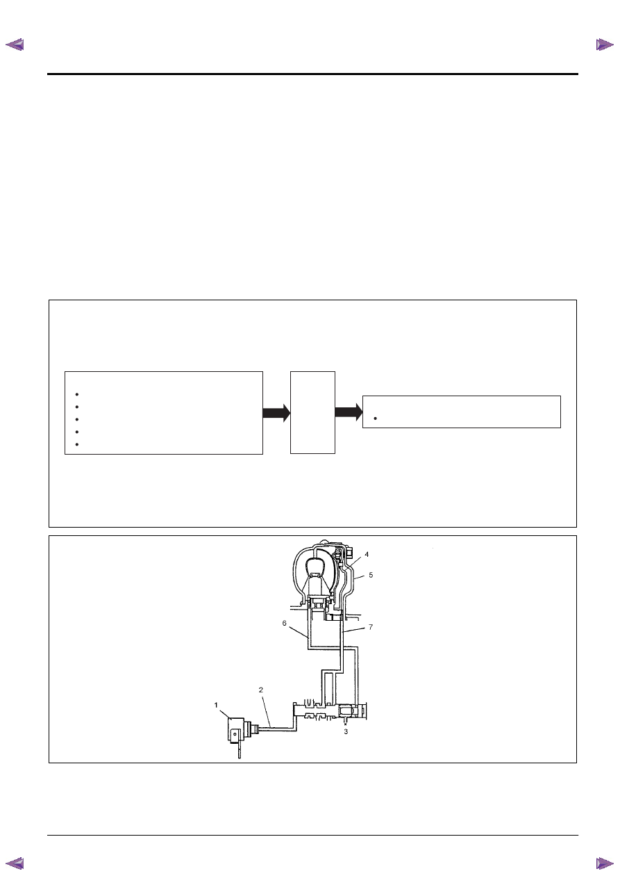
Lock Up Control
Legend
1. TCC solenoid valve
2. Solenoid fluid pressure
3. Lock up control spool valve
4. Torque converter clutch (TCC)
5. Torque converter front cover
6. TCC engagement fluid pressure
7. TCC disengagement fluid pressure
TCM
Sensor inputs
Input shaft speed (ISS) sensor
Output shaft speed (OSS) sensor
Transmission fluid temperature (TFT) sensor
Accelerator pedal position signal (via ECM)
Engine speed signal (via ECM)
Solenoid valve outputs
Torque converter clutch (TCC) solenoid valve
7A2-158 TRANSMISSION CONTROL SYSTEM (JR405E)
The TCM controls the torque converter clutch (TCC)
solenoid valve based on the accelerator pedal angle,
input shaft speed, output shaft speed and transmission
fluid temperature.
Smooth lock up control is employed to engage or
disengage the TCC smoothly at the time of lock up On
or Off. When the TCM determines the TCC
engagement, the solenoid valve control duty cycle
(pulse width modulation [PWM]) signal is gradually
increased (5% to 95%) and the transmission fluid
between the TCC piston and torque converter front
cover is gradually drained. As a result, the TCC piston
is fitted slowly to the torque converter front cover under
fluid pressure securing smooth lock up engagement.
The lock up control does not start when the
transmission fluid temperature is less than 20
°C (68°F)
even though the vehicle is at the lock up control speed
area. The lock up control disengages when the
accelerator pedal angle is released.
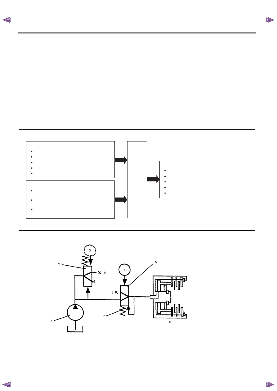
Direct Electronic Shift Control (DECS)
Legend
1. Oil pump
2. Pressure regulator spool valve
3. ON/ OFF type solenoid valve (pressure control [PC]
solenoid valve
4. Duty cycle type solenoid valve (shift solenoid valve)
5. Amplifier (AMP) valve
6. Clutch
Solenoid valve outputs
Pressure control (PC) solenoid valve
Low & reverse brake solenoid valve
2-4 brake solenoid valve
High clutch solenoid valve
Low clutch solenoid valve
TCM
Sensor inputs
Input shaft speed (ISS) sensor
Output shaft speed (OSS) sensor
Transmission fluid temperature (TFT) sensor
Accelerator pedal position signal (via ECM)
Engine speed signal (via ECM)
Switch inputs
Low & reverse brake transmission fluid
pressure (TFP) switch
2-4 brake transmission fluid pressure (TFP)
switch
High clutch transmission fluid pressure (TFP)
switch
TRANSMISSION CONTROL SYSTEM (JR405E) 7A2-159
Based on each transmission fluid pressure (TFP)
switch signal and each speed sensor signal and the
accelerator pedal angle, the duty cycle type shift
solenoid valve adjusts the clutch pressure to match the
engine load and vehicle running conditions. Controlling
the engagement and disengagement of the clutch and
brake pressure is directly and accurately controlled via
TCM, which is different to the conventional accumulator
type. Instead of the conventional system (On/ Off type
shift solenoid valve and shift valve), the combination of
the duty cycle type solenoid valve and the amplifier
(AMP) valve are used to adjust the clutch pressure to
match the engine load and vehicle driving conditions,
based on the signal from the TCM. Also, the TFP
switch provided in the fluid passage of the control valve
transmits to TCM, enabling the engagement and
disengagement control of the clutch and brake to be
directly and finely. When the gear is shifted from the
2nd to 3rd, 3rd to 4th, 4th to 3rd and 3rd to 2nd, the
clutch pressures on the engagement side and
disengagement side are simultaneously controlled. As
a result, engine racing or clutch drag is prevented
which enables a smooth and quick shift response.
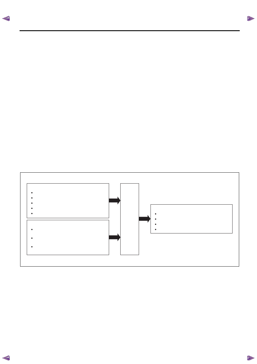
Learning Control
Solenoid valve outputs
Low & reverse brake solenoid valve
2-4 brake solenoid valve
High clutch solenoid valve
Low clutch solenoid valve
TCM
Sensor inputs
Input shaft speed (ISS) sensor
Output shaft speed (OSS) sensor
Transmission fluid temperature (TFT) sensor
Accelerator pedal position signal (via ECM)
Engine speed signal (via ECM)
Switch inputs
Low & reverse brake transmission fluid
pressure (TFP) switch
2-4 brake transmission fluid pressure (TFP)
switch
High clutch transmission fluid pressure (TFP)
switch
Нет комментариевНе стесняйтесь поделиться с нами вашим ценным мнением.
Текст