Isuzu KB P190. Manual — part 1379
8A-578 ELECTRICAL-BODY AND CHASSIS
KEYLESS ENTRY CONTROL UNIT
Removal
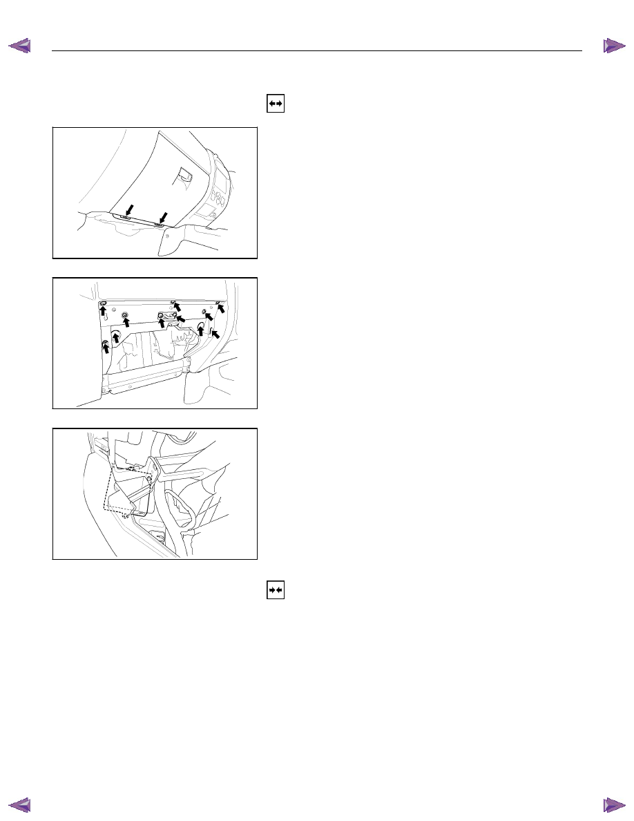
1. Remove the glove box.
RTW580SH001601
2. Disconnect the glove box lamp connector.
RTW580SH001701
3. Remove the glove box cover.
RTW580SH001801
4. Remove the bolt of antitheft and keyless entry control unit.
5. Disconnect the antitheft and keyless entry control unit
connector.
6. Remove the antitheft and keyless entry control unit.
Installation
Follow the removal procedure in the reverse order to install the
antitheft and keyless entry control unit.
Connector
Be absolutely sure that the antitheft and keyless entry control
unit harness connector is correctly installed.
This will prevent a poor contact and an open circuit.

ELECTRICAL-BODY AND CHASSIS 8A-579
Remote key
Remove Key Assembly
Replacing the battery in the remote control unit
Replace the battery as soon as the range of the remote control
starts to become reduced.
Open the underside of the remote control unit by removing the
battery cover with a screwdriver as shown in the illustration.
Replace the battery, ensuring that it is inserted correctly.
Replace the battery cover so that it engages audibly. The
battery change must be performed within 3 minutes, otherwise
the remote control will have to be reprogrammed. Make sure
that you dispose of old batteries in accordance with
environmental protection regulations.
604RW055
8A-580 ELECTRICAL-BODY AND CHASSIS
TECH-2 OPERATION AND PROGRAMING
KEYLESS ENTRY
General Description
When the anti-theft and keyless entry control unit and/or the
transmitters (remote keys) are replaced, the security codes
and/or transmitter ID codes must be programmed by using he
Tech-2. The following pages show the procedures to program
in regard to the anti-theft and keyless entry system. Please
refer to Tech-2 scan tool user’s guide in detail.
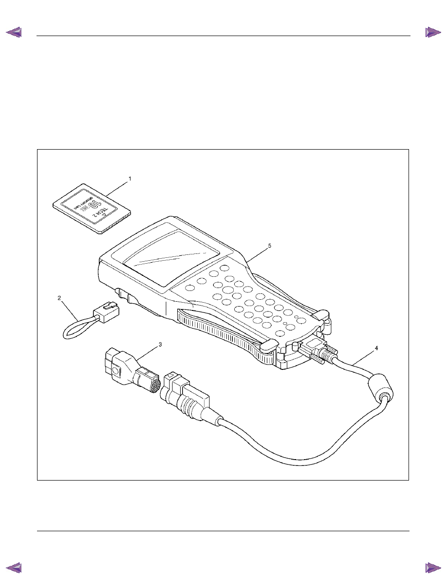
901RW180
Legend
(1) PCMCIA Card
(4) DLC Cable
(2) RS 232 Loop Back Connector
(5) Tech–2
(3) SAE 16/19 Adaptor
ELECTRICAL-BODY AND CHASSIS 8A-581
060RW009
Tech-2 Features
1. Tech-2 is a 12volt system. Do not apply 24 volts.
2. After connecting and/or installing the vehicle
communication interface (VCI) module, PCMCIA
card and data link connector (DLC) to the Tech-
2, connect the tool to the vehicle DLC.
3. Make sure the Tech-2 is OFF when removing or
installing the PCMCIA card.
4. The Tech-2 has the capability of two snapshot.
5. The PCMCIA card is sensitive to magnetism and
static electricity, so care should be taken in the
handling of the card.
6. The Tech-2 can not plot a graph when replaying
a snapshot.
7. Always return to the Main Menu by pressing the
EXIT key several times before shutting down.
8. To clear diagnostic trouble codes (DTCs), open
Application Menu and press "Clear DTC ".
060R300015
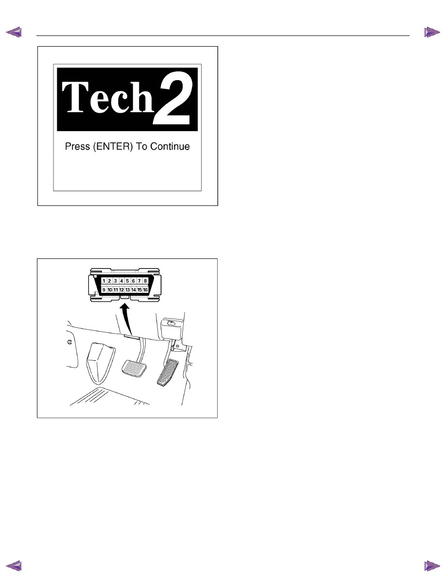
Getting Started
Before operating the Isuzu PCMCIA card with the
Tech-2, the following steps must be performed:
1. The Isuzu System PCMCIA card inserts into the
Tech-2.
2. Connect the SAE 16/19 adapter to the DLC
cable.
3. Connect the DLC cable to the Tech-2.
4. Mark sure the vehicle ignition is off.
5. Connect the Tech-2 SAE 16/19 adapter to the
vehicle DLC.
Нет комментариевНе стесняйтесь поделиться с нами вашим ценным мнением.
Текст