Isuzu KB P190. Manual — part 1174
7B1-90 MANUAL TRANSMISSION
Disassembly
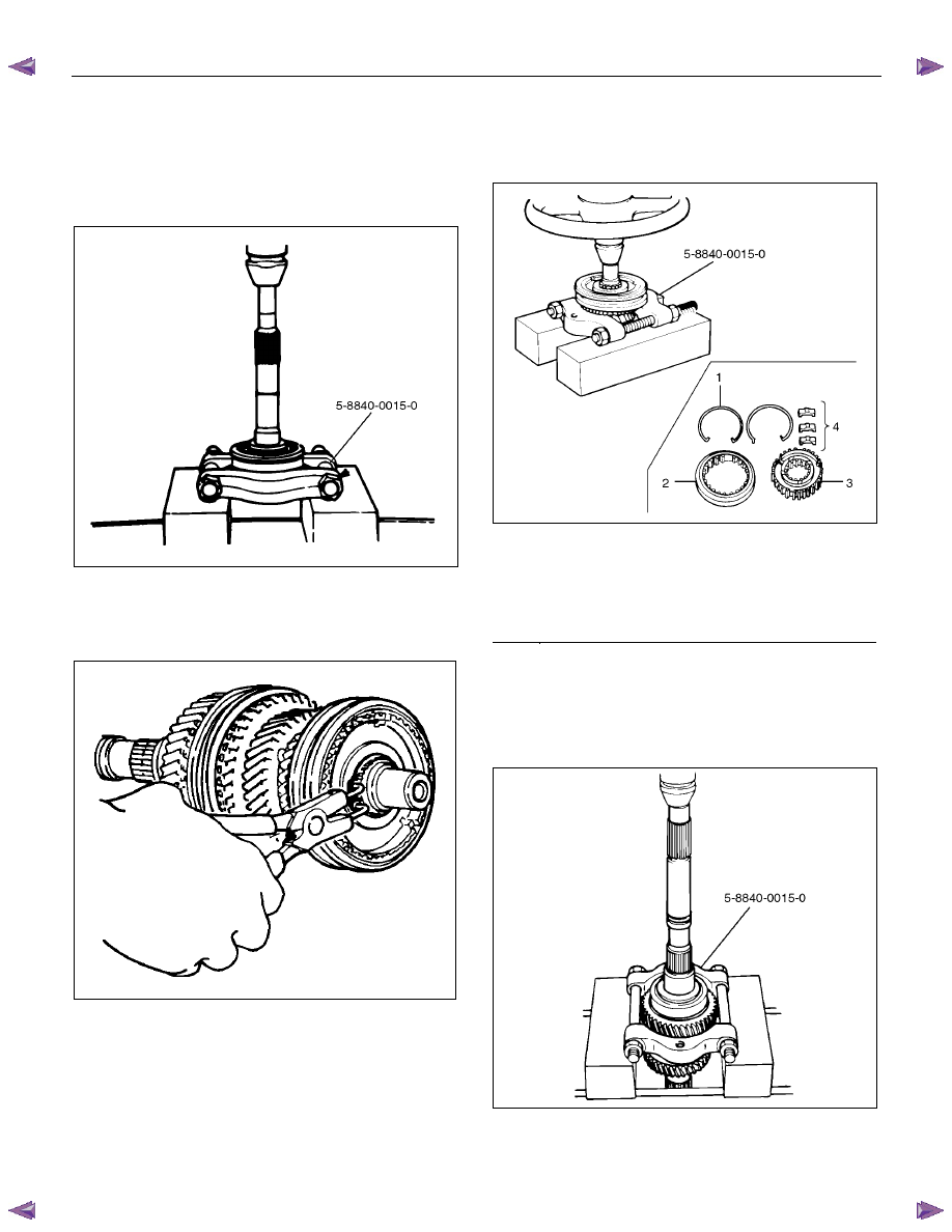
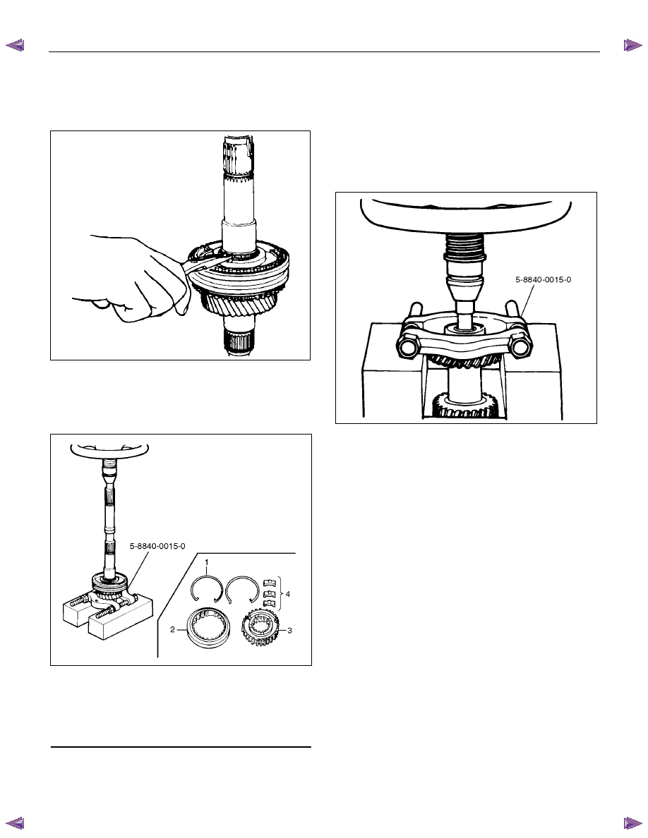
1. Use a pair of snap ring pliers to remove the top gear
shaft snap ring.
2. Remove the top gear shaft with ball bearing.
3. Use a bench press and the bearing remover 5-8840-
0015-0 to remove the ball bearing.
226RW216
4. Remove the needle bearing and top block ring,
mainshaft snap ring.
5. Use a pair of snap ring pliers to remove the
mainshaft snap ring.
226RS008
6. Use a bench press and the bearing remover 5-8840-
0015-0 to remove the 3rd-4th synchronizer
assembly as a set.
Disassemble the synchronizer assembly.
226RW217
Legend
(1)
Springs
(2)
Sleeve
(3)
Clutch Hub
(4)
Inserts
7. Remove the 3rd block ring, 3rd gear, and needle
bearing.
8. Use a bench press and the bearing remover 5-8840-
0015-0 to remove the 1st gear together with the
mainshaft ball bearing, 1st gear thrust bearing, and
the needle bearing collar.
226RW218
MANUAL TRANSMISSION 7B1-91
9.Disassemble the 1st inside ring, 1st outside ring, and
1st block ring.
10.Remove the needle bearing.
11.Use a pair of snap ring pliers to remove the clutch
hub snap ring.
226RS031
12.Use a bench press and the bearing remover 5-8840-
0015-0 to remove the 2nd gear together with 1st-2nd
synchronizer assembly, 2nd block ring, 2nd outside
ring, and inside ring.
Disassemble the synchronizer assembly.
226RW220
Legend
(1) Springs
(2) Sleeve
(3) Clutch
Hub
(4) Inserts
13. Remove the needle bearing from the mainshaft.
14. Remove the bearing snap ring.
15. Remove the front roller bearing by performing the
following steps.
• Remove the ring, outer race and bearing
assembly by using a bench press and remover
5-8840-0015-0.
• Remove the inner race by using a bench press
and remover 5-8840-0015-0.
226RW219
16. Remove the center roller bearing from the counter
gear shaft.
7B1-92 MANUAL TRANSMISSION
Inspection and Repair
Make the necessary adjustments, repairs, and part
replacements if excessive wear or damage is
discovered during inspection.
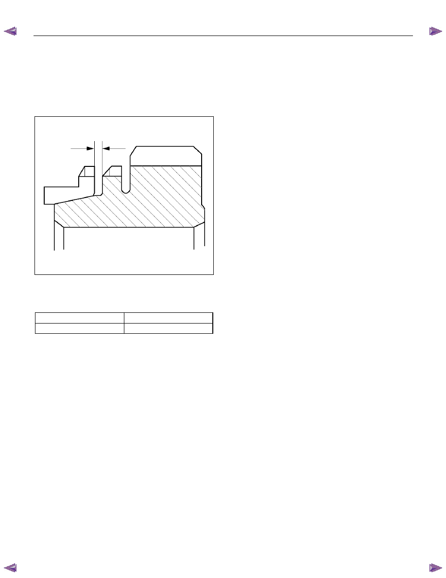
Block Ring and Dog Teeth Clearance
• Use a thickness gauge to measure the clearance
between the block ring and the dog teeth.
226RS035
If the measured value exceeds the specified limit,
the block ring must be replaced.
Block Ring and Dog Teeth Clearance
Standard Limit
1.5 mm (0.059 in)
0.8 mm (0.031 in)
MANUAL TRANSMISSION 7B1-93
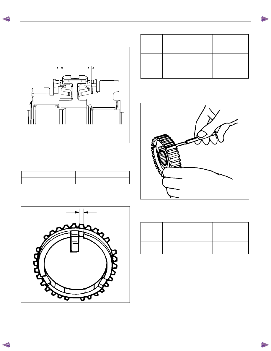
1st-2nd Synchronizer (3-CONE)
• Use a thickness gauge to measure the clearance
between the block ring and the dog teeth.
226RS036
If the measured value exceeds the specified limit,
the 1st-2nd synchronizer assembly must be
replaced.
Block Ring and Dog Teeth Clearance
Standard Limit
1.5 mm (0.059 in)
0.8 mm (0.031 in)
Block Ring and Insert Clearance
• Use a vernier caliper or thickness gauge to measure
the clearance between the block ring and the insert.
226RS037
If the measured value exceeds the specified limit,
the block ring and the insert must be replaced.
Block and Insert Clearance
Standard Limit
3rd-4th
3.46 - 3.76 mm
(0.136 - 0.148 in)
4.0 mm
(0.157 in)
1st-2nd
3.86 – 4.16 mm
(0.152 - 0.164 in)
4.9 mm
(0.193 in)
Rev.5th
3.59 - 3.91 mm
(0.141 - 0.154 in)
4.1 mm
(0.161 in)
Clutch Hub and Insert Clearance
• Use a thickness gauge to measure the clearance
between the clutch hub and the insert.
226RS038
If the measured value exceeds the specified limit,
the clutch hub and the insert must be replaced.
Clutch Hub and Insert Clearance
Standard Limit
1st-2nd
3rd-4th
0.01 – 0.21 mm
(0.0004 - 0.0083 in)
0.3 mm
(0.012 in)
Rev-5th
0.09 – 0.31 mm
(0.0035 - 0.0122 in)
0.4 mm
(0.016 in)
Нет комментариевНе стесняйтесь поделиться с нами вашим ценным мнением.
Текст