Isuzu KB P190. Manual — part 951

Automatic Transmission – 4L60E – Electrical Diagnosis
Page 7C2–18
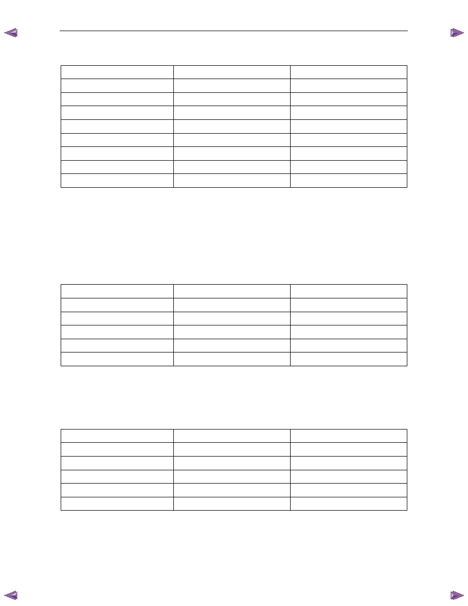
Tech 2 Parameter
Units Displayed
Typical Data Value
Transmission Fluid Temp
°C
Varies
Estimated Gear Ratio
Ratio
8.00:1
Transmission Hot Mode
On / Off
Off
1-2 Shift Data
Once this mode is selected, displays specific parameter information about the 1-2 shift solenoid valve and its circuits.
1-2 Shift Data Parameters
For definitions of the parameters in this table, refer to 3.3
Tech 2 Data Definitions.
Tech 2 Parameter
Units Displayed
Typical Data Value
Shift Solenoid A
On / Off
Varies
Shift Solenoid B
On / Off
Varies
Commanded Gear
1,2,3,4
1
1-2 Shift Time
Seconds
Varies
1-2 Shift Error
Seconds
Varies
Shift Solenoid A Circuit
Open or Shorted / Short to Battery /
Okay
Okay
Throttle Position
Percent
Varies
Engine Speed
RPM
Varies
AT Input Speed
N/A
N/A
AT Output Speed
RPM
Varies
Vehicle Speed
km/h
0
Estimated Gear Ratio
Ratio
8.00:1
2-3 Shift Data
Once this mode is selected, displays specific parameter information about the 2-3 shift solenoid valve and its circuits.
2-3 Shift Data Parameters
For definitions of the parameters in this table, refer to 3.3
Tech 2 Data Definitions.
Tech 2 Parameter
Units Displayed
Typical Data Value
Shift Solenoid A
On / Off
Varies
Shift Solenoid B
On / Off
Varies
Commanded Gear
1,2,3,4
1
2-3 Shift Time
Seconds
Varies
2-3 Shift Error
Seconds
Varies
Shift Solenoid B Circuit
Open or Shorted / Short to Battery /
Okay
Okay
Throttle Position
Percent
Varies
Engine Speed
RPM
Varies
AT Input Speed
N/A
N/A
AT Output Speed
RPM
Varies

Automatic Transmission – 4L60E – Electrical Diagnosis
Page 7C2–19
Tech 2 Parameter
Units Displayed
Typical Data Value
Vehicle Speed
km/h
0
Estimated Gear Ratio
Ratio
8.00:1
3-4 Shift Data
Once this mode is selected, displays information on 3-4 shift timing.
3-4 Shift Data Parameters
For definitions of the parameters in this table, refer to 3.3
Tech 2 Data Definitions.
Tech 2 Parameter
Units Displayed
Typical Data Value
Shift Solenoid A
On / Off
Varies
Shift Solenoid B
On / Off
Varies
Commanded Gear
1,2,3,4
1
3-4 Shift Time
Seconds
Varies
3-4 Shift Error
Seconds
Varies
Throttle Position
Percent
Varies
Engine Speed
RPM
Varies
AT Input Speed
N/A
N/A
AT Output Speed
RPM
Varies
Vehicle Speed
km/h
0
Estimated Gear Ratio
Ratio
8.00:1
3-2 Downshift Data
Once this mode is selected, displays information on 3-2 downshift timing.
3-2 Downshift Data Parameters
For definitions of the parameters in this table, refer to 3.3
Tech 2 Data Definitions.
Tech 2 Parameter
Units Displayed
Typical Data Value
3-2 Downshift Solenoid
On / Off
Varies
Commanded Gear
1,2,3,4
1
3-2 Downshift Solenoid Circuit
Open or Shorted / Short to Battery /
Okay
Okay
Throttle Position
Percent
Varies
Engine Speed
RPM
Varies
AT Input Speed
N/A
N/A
AT Output Speed
RPM
Varies
Vehicle Speed
km/h
0
Estimated Gear Ratio
Ratio
8.00:1
Pressure Control Solenoid Data
Displays specific parameter information about the PC solenoid and its circuits.
Automatic Transmission – 4L60E – Electrical Diagnosis
Page 7C2–20
Pressure Control Solenoid Data Parameters
For definitions of the parameters in this table, refer to 3.3
Tech 2 Data Definitions.
Tech 2 Parameter
Units Displayed
Typical Data Value
PCS Actual Current
Amps
Varies (0.1 – 1.1 A)
PCS Desired Current
Amps
Varies (0.1 – 1.1 A)
PCS Duty Cycle
Percent
Varies
Engine Speed
RPM
Varies
Transmission Fluid Temp
°C
Varies
Throttle Position
Percent
Varies
Vehicle Speed
km/h
0
Commanded Gear
1,2,3,4
1
Transmission Adapts
Once this is selected, it has further sub menus.
1-2 Adapt Data
In this mode Tech 2 continuously monitors and displays 1-2 TAP cell data parameters.
1-2 Adapt Data Parameter
For definitions of the parameters in this table, refer to 3.3
Tech 2 Data Definitions.
Tech 2 Parameter
Units Displayed
Typical Data Value
1-2 Shift Time
Seconds
Varies
1-2 Shift Error
Seconds
Varies
Current TAP Cell
4-16
Varies
Throttle Position
Percent
Varies
1-2 Tap Cell (1 – 17)
kPa
Varies
2-3 Adapt Data
In this mode Tech 2 continuously monitors and displays 2-3 TAP cell data parameters.
2-3 Adapt Data Parameters
For definitions of the parameters in this table, refer to 3.3
Tech 2 Data Definitions.
Tech 2 Parameter
Units Displayed
Typical Data Value
2-3 Shift Time
Seconds
Varies
2-3 Shift Error
Seconds
Varies
Current TAP Cell
4-16
Varies
Throttle Position
Percent
Varies
2-3 Tap Cell (1 – 17)
kPa
Varies
3-4 Adapt Data
In this mode Tech 2 continuously monitors and displays 3-4 TAP cell data parameters.
3-4 Adapt Data Parameters
For definitions of the parameters in this table, refer to 3.3
Tech 2 Data Definitions.

Automatic Transmission – 4L60E – Electrical Diagnosis
Page 7C2–21
Tech 2 Parameter
Units Displayed
Typical Data Value
3-4 Shift Time
Seconds
Varies
3-4 Shift Error
Seconds
Varies
Current TAP Cell
4-16
Varies
Throttle Position
Percent
Varies
3-4 Tap Cell (1 – 17)
kPa
Varies
Steady State Adapt Data
In this mode TECH 2 continuously monitors and displays Steady State TAP data parameters.
Steady State Adapt Data Parameters
For definitions of the parameters in this table, refer to 3.3
Tech 2 Data Definitions.
Tech 2 Parameter
Units Displayed
Typical Data Value
Current TAP Cell
4-16
Varies
Throttle Position
Percent
Varies
Gear (1-4) TAP Cell
kPa
Varies
TCC (1-4) TAP Cell
kPa
Varies
Reverse Gear TAP Cell
kPA
Varies
3.3
Tech 2 Data Definitions
1-2 Shift Error: This parameter displays the difference between the desired 1-2 shift time and the actual 1-2 shift time. A
positive number indicates a firm or fast shift and the actual shift time was shorter than the desired shift time. A negative
number indicates a soft or slow shift and the actual shift time was longer than the desired shift time. This value is only
accurate if the shift was adaptable.
1-2 Shift Time: This parameter displays the actual time of the last 1-2 shift. The shift time is based on the engine r.p.m.
drop after the commanded 1-2 shift. This value is only accurate if the shift was adaptable.
1-2 TAP Cell (1-17): This parameter displays the amount of transmission adaptive pressure (TAP), based on 17 Nm of
engine torque increment per cell, added to or subtracted from shift pressure during a 1-2 upshift. A positive number
indicates that long shifts have been detected and PC solenoid pressure has been added to decrease shift time. A
negative number indicates that short shifts have been detected and PC solenoid pressure has been subtracted to
increase shift time.
2-3 Shift Error: This parameter displays the difference between the desired 2-3 shift time and the actual 2-3 shift time. A
positive number indicates a firm or fast shift, the actual shift time was shorter than the desired shift time. A negative
number indicates a soft or slow shift, the actual shift time was longer than the desired shift time. This value is only
accurate if the shift was adaptable.
2-3 Shift Time: This parameter displays the actual time of the last 2-3 shift. The shift time is based on the engine r.p.m
drop after the commanded 2-3 shift. This value is only accurate if the shift was adaptable.
2-3 TAP Cell (1-17): This parameter displays the amount of transmission adaptive pressure (TAP), based on 17 Nm of
engine torque increment per cell, added to or subtracted from shift pressure during a 2-3 upshift. A positive number
indicates that long shifts have been detected and PC solenoid pressure has been added to decrease shift time. A
negative number indicates that short shifts have been detected and PC solenoid pressure has been subtracted to
increase shift time.
3-4 Shift Error: This parameter displays the difference between the desired 3-4 shift time and the actual 3-4 shift time. A
positive number indicates a firm or fast shift, the actual shift time was shorter than the desired shift time. A negative
number indicates a soft or slow shift, the actual shift time was longer than the desired shift time. This value is only
accurate if the shift was adaptable.
3-4 Shift Time: This parameter displays the actual time of the last 3-4 shift. The shift time is based on the engine r.p.m.
drop after the commanded 3-4 shift. This value is only accurate if the shift was adaptable.
3-4 TAP Cell (1-17): This parameter displays the amount of transmission adaptive pressure (TAP), based on 17 Nm of
engine torque increment per cell, added to or subtracted from shift pressure during a 3-4 upshift. A positive number
indicates that long shifts have been detected and PC solenoid pressure has been added to decrease shift time. A
Нет комментариевНе стесняйтесь поделиться с нами вашим ценным мнением.
Текст