Isuzu KB P190. Manual — part 950
Automatic Transmission – 4L60E – Electrical Diagnosis
Page 7C2–14
3
Tech 2 Information
3.1
Tech 2 Diagnostics
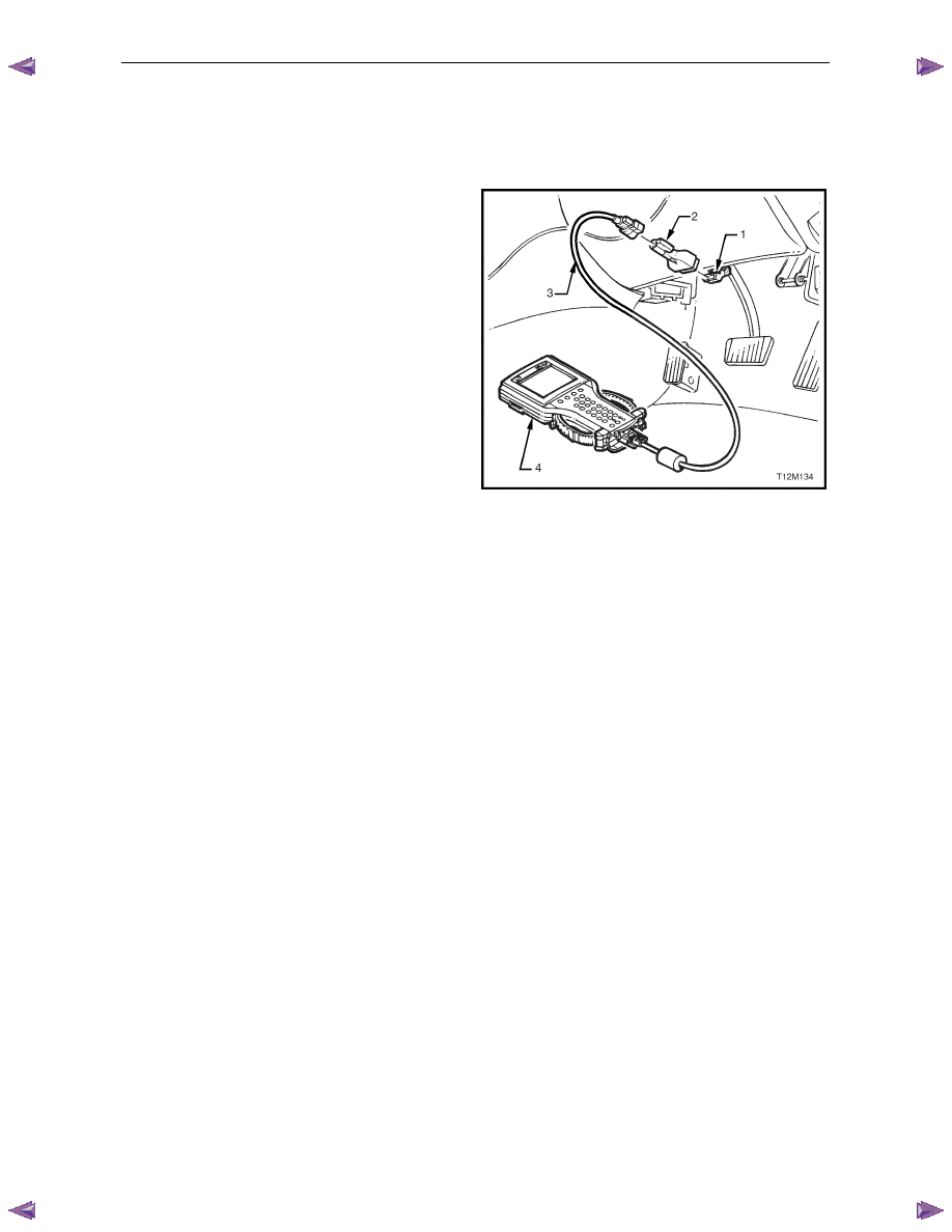
Tech 2, with the appropriate software, cables and adapters,
when connected to the serial data link connector (DLC) can
read seat and exterior rear-view mirror serial data. The DLC
is attached to the instrument panel trim retainer beneath the
steering wheel.
1 DLC
2 DLC
Adapter
3 DLC
Cable
4 Tech
2
For additional general information on connecting and
operating Tech 2, refer to 0C Tech 2.
Figure 1A7 – 3
Test Modes
Tech 2 has six test modes for diagnosing the transmission. To get to these various test modes, on Tech 2 select:
Diagnostics / Model Year / Model / Vehicle Type / Transmission / Automatic Transmission
and follow Tech 2’s prompts. This will then display the following menu operations.
Diagnostic Trouble Codes
If Diagnostic Trouble Codes is selected, a selection list is displayed which contains:
•
Read DTC Information – Once selected, both current and history diagnostic trouble codes (DTCs) stored in the
transmission control module will be displayed.
•
Clear Engine & Transmission DTC(s) – Once selected, DTCs stored in the transmission control module (TCM)
and engine control module (ECM) memory may be cleared.
•
Freeze Frame / Failure Records – Shows Freeze Frame / Failure Records information. Freeze Frame / Failure
Records are types of snapshots stored in the memory of the TCM and contain data parameters from the TCM at
the time the DTC set.
N O T E
For a complete list of TCM DTCs, refer to
4.8
Diagnostic Trouble Code List. For
further information on Tech 2 and it functions,
refer to 0C Tech 2.
Data Display
If Data Display is selected, a selection list is displayed which contains:
•
Transmission Data – Once is selected, a list of transmission components and the TCM inputs are displayed along
with their status.
•
TCC Data – Once selected, displays specific parameter information about the torque converter clutch controlling
devices and their circuits.
•
1-2 Shift Data – Once selected, displays specific parameter information about the 1-2 shift solenoid valve (shift
solenoid A) and its circuits.
Automatic Transmission – 4L60E – Electrical Diagnosis
Page 7C2–15
•
2-3 Shift Data – Once this mode is selected, displays specific parameter information about the 2-3 shift solenoid
valve (shift solenoid B) and its circuits.
•
3-4 Shift Data – Once selected, displays information on 3-4 shift timing.
•
3-2 Downshift Data – Once selected, displays information on 3-2 downshift timing.
•
Pressure Control Solenoid Data – Once selected, displays specific parameter information about the PC solenoid
and its circuits.
•
Transmission Adapts – Once selected, it has further sub menus:
•
1-2 Adapt Data – In this mode Tech 2 continuously monitors and displays 1-2 TAP cell data parameters.
•
2-3 Adapt Data –In this mode Tech 2 continuously monitors and displays 2-3 TAP cell data parameters.
•
3-4 Adapt Data –In this mode Tech 2 continuously monitors and displays 3-4 TAP cell data parameters.
•
Steady State Adapt Data – In this mode Tech 2 continuously monitors and displays Steady State TAP data
parameters.
•
System Identification: In this mode, Tech 2 will display the transmission identification screen. The following items
will be displayed; Identifier, Partnumber, Hardware Partnumber, Alpha Code, Software Version Number, Software
Partnumber, VIN Digit 1-10, VIN Digit 11-17.
N O T E
Further information about the Data Display mode
and the data parameter is contained in
3.2 Data
Display.
Snapshot
In this test mode, Tech 2 captures TCM data before and after a forced manual trigger.
Additional Functions
If Additional Functions is selected, a selections list is displayed which contains:
•
System Identification– In this mode, Tech 2 will display the transmission identification screen. The following items
will be displayed; Identifier, Partnumber, Hardware Partnumber, Alpha Code, Software Version Number, Software
Partnumber.
Miscellaneous Tests
If Miscellaneous Functions is selected, a selections list is displayed which contains:
•
TCC Solenoid –Tech 2 can command the TCC solenoid on and off. Tech 2 will display whether the TCC solenoid
is active or inactive.
•
TCC PWN Solenoid – Tech 2 can command the TCC PWM solenoid on and off. Tech 2 will display whether the
TCC PWM solenoid is active or inactive and torque percentage.
•
TCC Apply – Tech 2 can command the TCC on when the vehicle is above 50 km/h.
•
Shift Solenoid A – Tech 2 can command the shift solenoid A (1-2 shift solenoid) on and off.
•
Shift Solenoid B – Tech 2 can command the shift solenoid B (2-3 shift solenoid) on and off.
•
3/2 Downshift Solenoid – Tech 2 can command the 3/2 downshift solenoid (3-2 shift solenoid) on and off.
•
Gear Control – Tech 2 can incrementally command shift solenoid states to correspond to relative gear states. The
TCM will only allow single shift increments or decrements and does not allow a shift if it causes the engine RPM to
exceed a calibrated limit.
•
Pressure Control Solenoid – This function allows the user to control state of the pressure control solenoid in
increments of 100 mA.
N O T E
For operating parameters of the
Miscellaneous
Test, refer to 3.4 Miscellaneous Tests.

Automatic Transmission – 4L60E – Electrical Diagnosis
Page 7C2–16
Programming
If Programming is selected, a selection list is displayed which contains:
•
Reset TAP Cells – This test allows the user to reset the Transmission Adapt (TAP) cells by pressing the Reset soft
key.
N O T E
Upon resetting the TAP cells the TCM loses all
learnt adaptive functions. When the vehicle is first
driven after this, the shifts may be harsh. This
harshness will ease as the TCM relearns the TAP
cells.
3.2 Data
Display
If Data Display is selected, a selection list is displayed which contains the following:
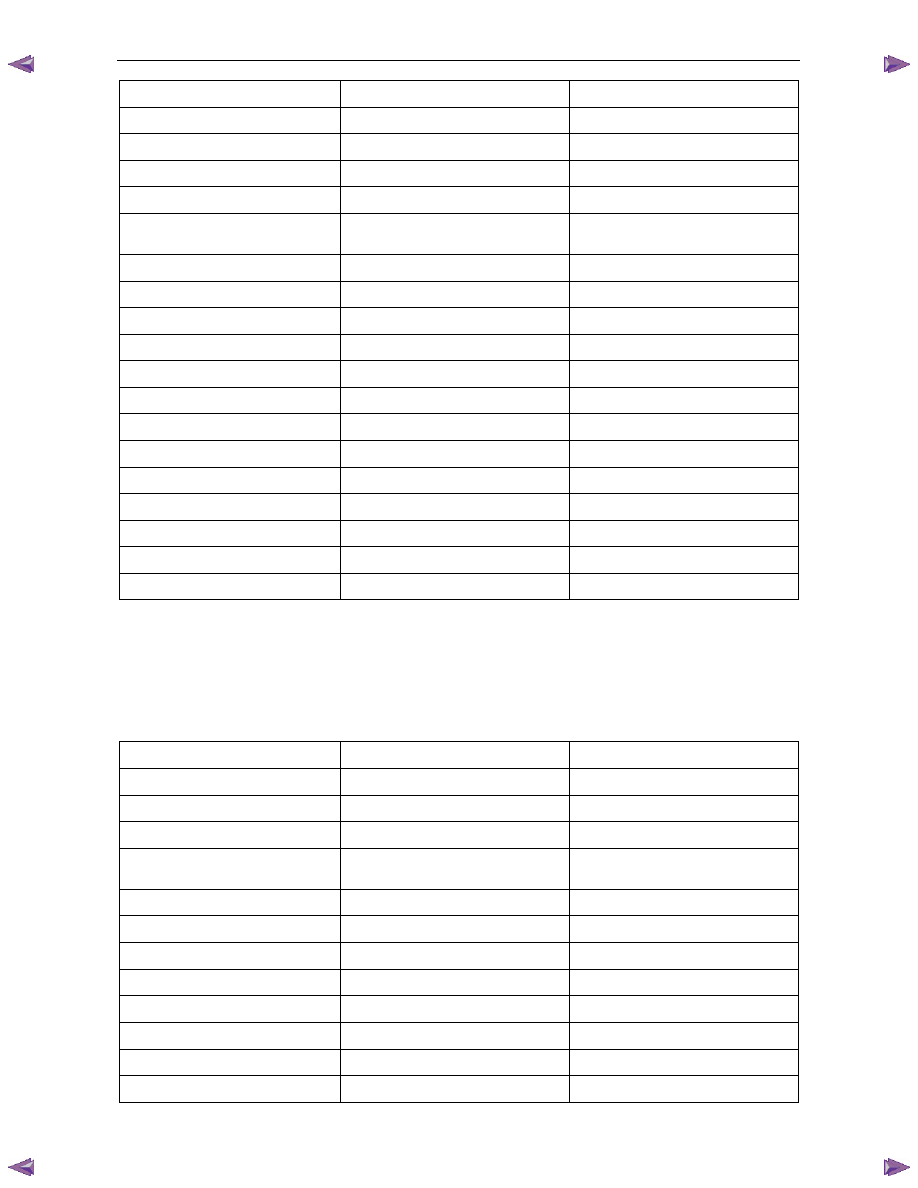
Transmission Data
Once this mode, a list of transmission components and the TCM inputs are displayed along with their status.
Transmission Data Parameters
For definitions of the parameters in this table, refer to 3.3
Tech 2 Data Definitions.
Tech 2 Parameter
Units Displayed
Typical Data Value
Engine Torque
Nm
Varies
Throttle Position
Percent
Varies
Engine Speed
RPM
Varies
AT Input Speed
N/A
N/A
AT Output Speed
RPM
Varies
Vehicle Speed
km/h
0
Commanded Gear
1,2,3,4
1
Shift Solenoid A
On / Off
Varies
Shift Solenoid B
On / Off
Varies
3-2 Downshift Solenoid
On/Off
On
Estimated Gear Ratio
Ratio
8.00:1
Speed Ratio
Ratio
8.00:1
Torque Converter Efficiency
Ratio
.00:1
TFP Switch A
Open 12 V / Closed 0 V
Varies
TFP Switch B
Open 12 V / Closed 0 V
Varies
TFP Switch C
Open 12 V / Closed 0 V
Varies
Engine Coolant Temperature
°C
Varies
Transmission Fluid Temp
°C
Varies
Transmission Hot Mode
On/Off
Off
PCS Actual Current
Amps
Varies (0.1 – 1.1 A)
PCS Desired Current
Amps
Varies (0.1 – 1.1 A)
PCS Duty Cycle
Percent
Varies
Automatic Transmission – 4L60E – Electrical Diagnosis
Page 7C2–17
Tech 2 Parameter
Units Displayed
Typical Data Value
High Side Driver 1
N/A
N/A
TCC Solenoid
On / Off
Varies
TCC PWM Solenoid
Percent
0%
TCC Slip Speed
RPM
+/-50 RPM from Engine Speed
Transmission Range (TR)
Park/Neutral, Reverse, Drive4,
Drive3, Drive2, Drive1 or Invalid
Park/Neutral
TR Switch A
Open 12 V / Closed 0 V
Varies
TR Switch B
Open 12 V / Closed 0 V
Varies
TR Switch C
Open 12 V / Closed 0 V
Varies
TR Switch P
Open 12 V / Closed 0 V
Varies
Latest Shift
Seconds
Varies
1-2 Shift Time
Seconds
Varies
2-3 Shift Time
Seconds
Varies
3-4 Shift Time
Seconds
Varies
Cruise Control
Active / Inactive
Varies
A/C Clutch
On / Off
Varies
Ignition Voltage
Volts
12-14 V
Shift Pattern
Normal / Power / Cruise
Varies
4 Wheel Drive Low
Active / Inactive
Inactive
TCC Data
Once this mode is selected, displays specific parameter information about the torque converter clutch controlling devices
and their circuits.
TCC Data Parameters
For definitions of the parameters in this table, refer to 3.3
Tech 2 Data Definitions.
Tech 2 Parameter
Units Displayed
Typical Data Value
TCC Solenoid
On / Off
Varies
TCC PWM Solenoid
Percent
0%
TCC Slip Speed
RPM
+/-50 RPM from Engine Speed
TCC Duty Cycle Circuit
Open or Shorted / Short to Battery /
Okay
Okay
Throttle Position
Percent
Varies
Engine Speed
RPM
Varies
AT Input Speed
N/A
N/A
AT Output Speed
RPM
Varies
Engine Torque
Nm
Varies
Vehicle Speed
km/h
0
Commanded Gear
1,2,3,4
1
Engine Coolant Temperature
°C
Varies
Нет комментариевНе стесняйтесь поделиться с нами вашим ценным мнением.
Текст