Isuzu KB P190. Manual — part 1001
7A2-38 TRANSMISSION CONTROL SYSTEM (AW30–40LE)
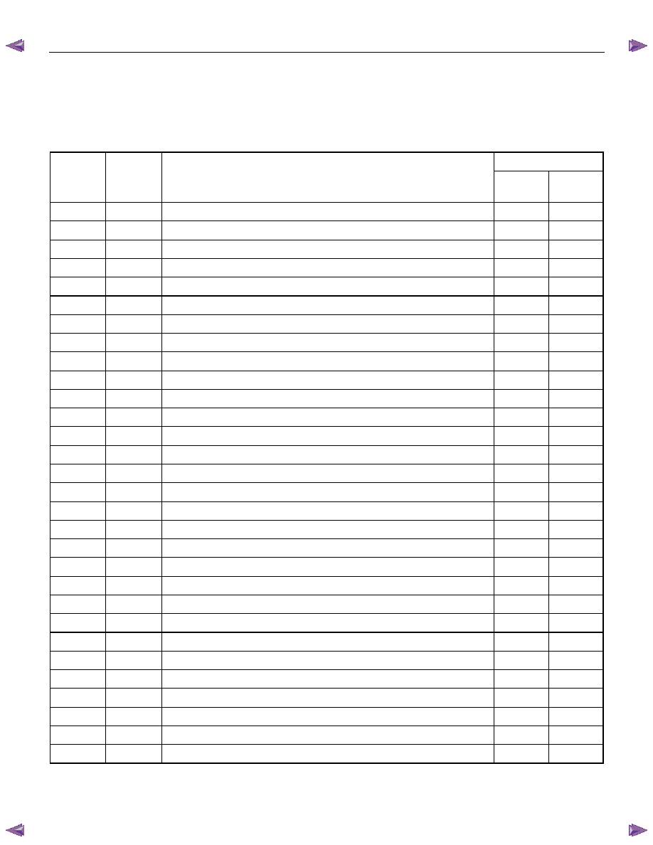
TCM Diagnostic Trouble Codes
The following table lists the diagnostic trouble codes supported by this vehicle application. If any DTCs not listed here
are displayed by a scan tool, the scan tool data may be faulty; notify the scan tool manufacture of any DTCs displayed
that are not included in the following table.
DTC Type
DTC No.
Flash
Code
DTC NAME
EURO 4
Except
EURO 4
P0562
72
System Voltage Error (Low)
E
E
P0563
73
System Voltage Error (High)
E
E
P0602
63
Transmission Control Module (TCM) Programming Error
E
E
P0707
17
Transmission Range Sensor Circuit Open
B
D
P0708
17
Transmission Range Sensor Circuit Short
B
D
P0712
15
Transmission Oil Temperature Circuit Short
B
D
P0713
16
Transmission Oil Temperature Circuit Open
B
D
P0717
14
Input Speed Sensor Signal Error
B
D
P0722
11
Output Speed Sensor Signal Error
B
D
P0741
43
Torque Converter Clutch Stuck “OFF”
B
F
P0742
53
Torque Converter Clutch Stuck “ON”
B
F
P0746
45
Pressure Control Solenoid F/B Stuck
B
D
P0751
41
Shift Solenoid S1 Stuck “OFF”
B D
P0752
51
Shift Solenoid S1 Stuck “ON”
B F
P0756
42
Shift Solenoid S2 Stuck “OFF”
B F
P0757
52
Shift Solenoid S2 Stuck “ON”
B F
P0962
35
Pressure Control Solenoid Circuit Open or GND Short
B F
P0963
35
Pressure Control Solenoid Circuit Ignition Short
B D
P0973
31
Shift Solenoid S1 Circuit GND Short
B D
P0974
31
Shift Solenoid S1 Circuit Open or Ignition Short
B D
P0976
32
Shift Solenoid S2 Circuit GND Short
B D
P0977
32
Shift Solenoid S2 Circuit Open or Ignition Short
B D
P1790
61
Transmission Control Module (TCM) ROM Checksum Error
B D
P1791
62
Transmission Control Module (TCM) RAM Error
B D
P2769
33
Torque Converter Clutch Circuit GND Short
B D
P2770
33
Torque Converter Clutch Circuit Open or Ignition Short
B D
P2773
75
Transfer 4L Switch Circuit GND Short
B D
P2774
75
Transfer 4L Switch Circuit Open or Ignition Short
B D
U2104
65
CAN BUS OFF
A
C
U2105
67
Lost of Communication with ECM
A
C
TRANSMISSION CONTROL SYSTEM (AW30–40LE) 7A2-39
Diagnostic Trouble Code (DTC) Type
Definitions
Emission Related DTC
Action Taken When the DTC Sets - Type A
• The Engine Control Module (ECM) illuminates the
malfunction indicator lamp (MIL) when the
diagnostic runs and fails.
• The ECM records the operating conditions at the
time the diagnostic fails. The ECM stores this
information in the Freeze Frame/ Failure Records.
Action Taken When the DTC Sets - Type B
• The ECM illuminates the MIL on the second
consecutive driving cycle when the diagnostic runs
and fails.
• The ECM records the operating conditions at the
time the diagnostic fails, the ECM stores this
information in the Failure Records. If the
diagnostic reports a failure on the second
consecutive driving cycle, the ECM records the
operating conditions at the time of failure and
stores this information in the Freeze Frame and
updates the Failure Records.
Conditions for Clearing the MIL/ DTC - Type A or
Type B
• The ECM turns OFF the MIL after 3 consecutive
driving cycles when the diagnostic runs and does
not fail. (Euro 4 Specification)
• The ECM turns OFF the MIL after 1 driving cycle
when the diagnostic runs and does not fail.
(Except Euro 4 Specification)
• A current DTC clears when the diagnostic runs
and passes after 1 driving cycle.
• A history DTC clears after 40 consecutive warm-
up cycles, if no failures are reported.
• Use a scan tool to clear the MIL and the DTC.
Non-Emissions Related DTCs
Action Taken When the DTC Sets - Type C or Type
D
• The TCM illuminates the Check Trans lamp when
the diagnostic runs and fails.
• The TCM records the operating conditions at the
time the diagnostic fails. The TCM stores this
information in the Failure Records.
• The TCM illuminates the Check Trans on the
second consecutive driving cycle when the
diagnostic runs and fails.
• The TCM records the operating conditions at the
time the diagnostic fails, the TCM stores this
information in the Failure Records. If the
diagnostic reports a failure on the second
consecutive driving cycle, the TCM records the
operating conditions at the time of failure and
stores this information in the Freeze Frame and
updates the Failure Records.
Conditions for Clearing the Check Trans Lamp/ DTC
- Type C or Type D
• The TCM turns OFF the Check Trans lamp after 1
driving cycle when the diagnostic runs and does
not fail.
• A current DTC clears when the diagnostic runs
and passes after 3 driving cycle.
• A history DTC clears after 40 consecutive warm-
up cycles, if no failures are reported.
• Use a scan tool to clear the Check Trans lamp and
the DTC.
Action Taken When the DTC Sets - Type E or Type F
• The TCM will not illuminate the Check Trans lamp.
• The TCM records the operating conditions at the
time the diagnostic fails. The TCM stores this
information in the Failure Records.
Conditions for Clearing the DTC - Type E or Type F
• A current DTC clears when the diagnostic runs
and passes after 1 driving cycle.
• A history DTC clears after 40 consecutive warm-
up cycles, if no failures are reported.
• Use a scan tool to clear the DTC.
7A2-40 TRANSMISSION CONTROL SYSTEM (AW30–40LE)
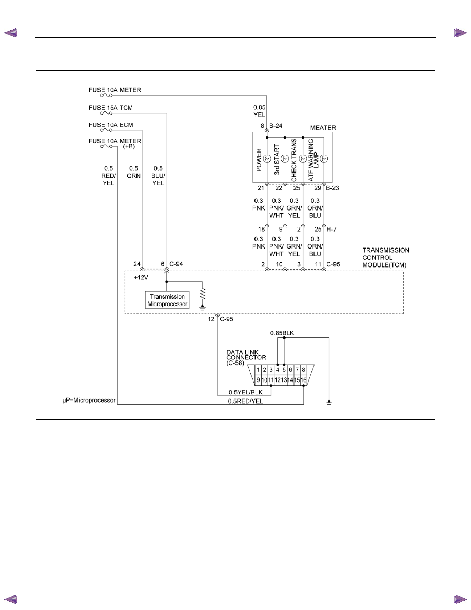
DTC P0562 or P0563 (Flash Code 72 or 73)
RTW77ALF001301
Circuit Description
The Transmission Control Module (TCM) monitors the
system voltage on the ignition feed terminal to the TCM.
A system voltage DTC will set whenever the voltage is
below or above a calibrated value.
Condition For Running The DTC
Ignition "ON" and either (1) or (2) conditions are met.
(1) All of the following conditions are met.
• DTC U2104 is not detecting failure of not
deciding failure.
• DTC U2105 is not detecting failure or not
deciding failure.
• Engine revolution signal is not detecting failure
or not deciding failure.
• The engine revolution is more than 1000rpm.
• All of the following conditions are met.
- Device Control is not operating
- Disable Normal Communication is receiving
enable
- DTC Clear is not operating
(2) All of the following conditions are met.
• Input revolution sensor is not detecting failure or
not deciding failure.
• Input revolution is more than 1000rpm.
TRANSMISSION CONTROL SYSTEM (AW30–40LE) 7A2-41
• All of the following conditions are met.
- Device Control is not operating
- Disable Normal Communication Service is
receiving enable
- DTC Clear is not operating
Condition For Setting The DTC
When the TCM detects following conditions at 20 times
continuously.
• Ignition voltage is less than 9 volts for 1 second or
more continuously. (DTC P0562)
• Ignition voltage is more than 18 volts for 1 second or
more continuously. (DTC P0563)
Action Taken When The DTC Sets
• DTC stored.
Conditions For Clearing The DTC
• The DTC can be cleared from the TCM history by
using a scan tool.
• The DTC will be cleared from history when the
vehicle has achieved 40 warm-up cycles without a
failure reported.
• After more than 1 second has elapsed after the
ignition key has been turned “ON”, short between
No.11 and No.4 (ground) of DLC (Data Link
Connector). Then, after 1 second, but within 6
seconds, discontinue shorting.
Diagnostic Aids
• Inspect the wiring for poor electrical connection at the
TCM. Look for possible bent, backed out, deformed
or damaged terminals. Check for weak terminal
tension as well. Also check for a chafed wire that
could short to bare metal or other wiring.
Inspect for a broken wire inside the insulation.
• When diagnosing for a possible intermittent short or
open condition, move the wiring harness while
observing test equipment for a change.
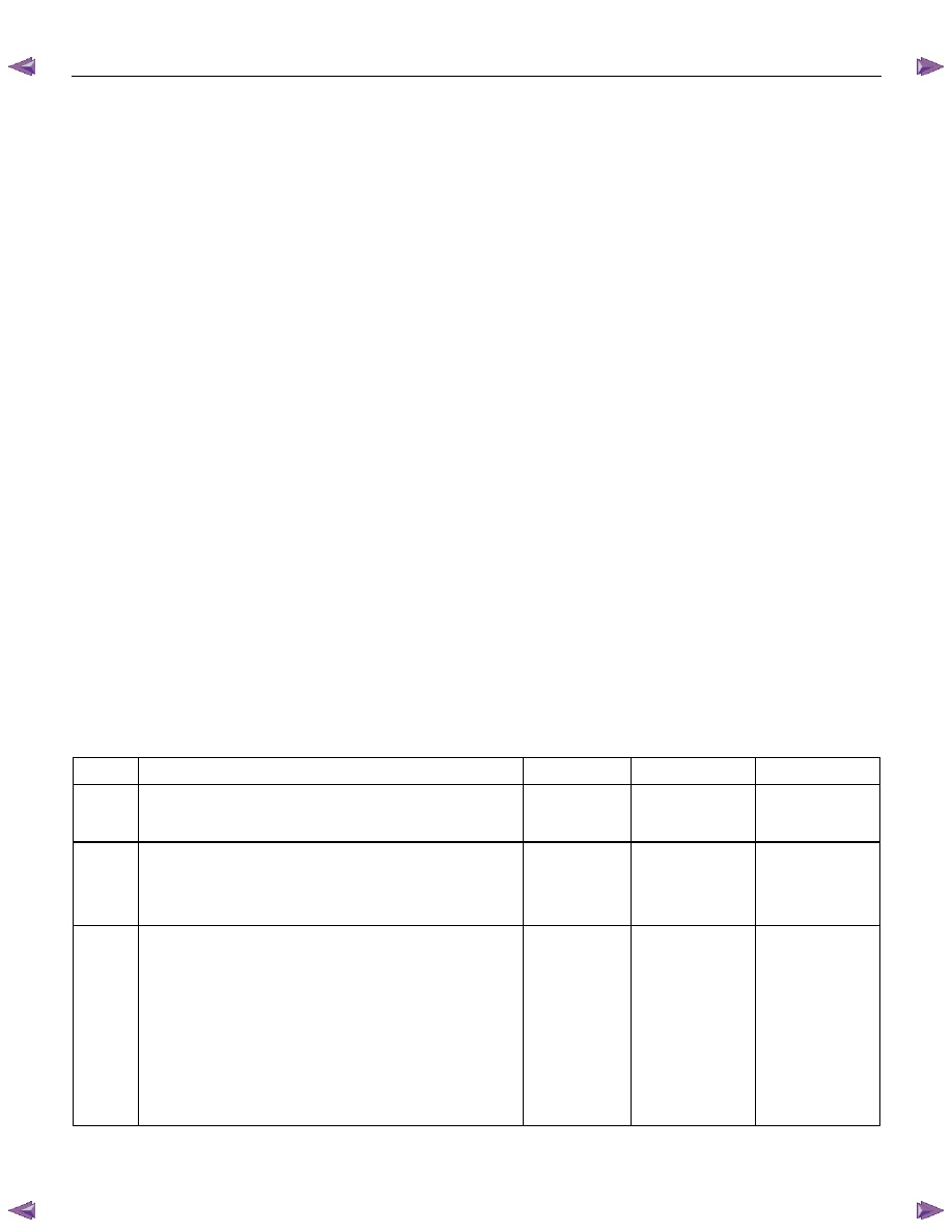
Circuit/System Testing DTC P0562 or P0563
Step Action Value(s)
YES
NO
1
Was the On-Board Diagnostic (OBD) System Check
performed?
—
Go to Step 2 Go
to
OBD
System Check
2
Using the 5-8840-0285-0 DMM, measure the battery
voltage at the battery.
Is the battery voltage greater than the specified value?
11.5 V
Go to Step 3
Charge battery,
then go to
Step 3
3
1. Install a scan tool.
2. Select “Ignition Volts” on a scan tool.
3. Start the engine and raise the engine speed to the
specified value.
4.
Load the electrical system by turning on the
headlights, high blower, etc.
Is the ignition voltage approximately equal to the
specified value?
More than
1000 rpm
9.0-18.0 V
Go to Step 4
Go to
Starting/
Charging
Нет комментариевНе стесняйтесь поделиться с нами вашим ценным мнением.
Текст